I’m sad, I’m super sad… Yesterday I finally had completed my first, custom build. Designed my own custom 3d printed chassis. Proffieboard v2, Bluetooth (with leds), OLED screen, USB-C charger+data, illuminated switches, neopixels, etc… Everything worked great. Played around for some time. Today the voltage went down to around 3.4v and I’ve put it to charge for about 2 hours. I was monitoring over bluetooth how it was charging (using ForceSync). Last I saw it got to 4.1v while charger connected. At some point everything turned off and doesn’t come back on anymore. Nothing. Except for a quick blink of the bluetooth LED whenever I switch the power on. Nothing lights up. The port doesn’t get recognized in Arduino port. Is the board fried? There are 3 layers of boards in this chassis… would be a nightmare to take things apart… Some photos below. Thanks.
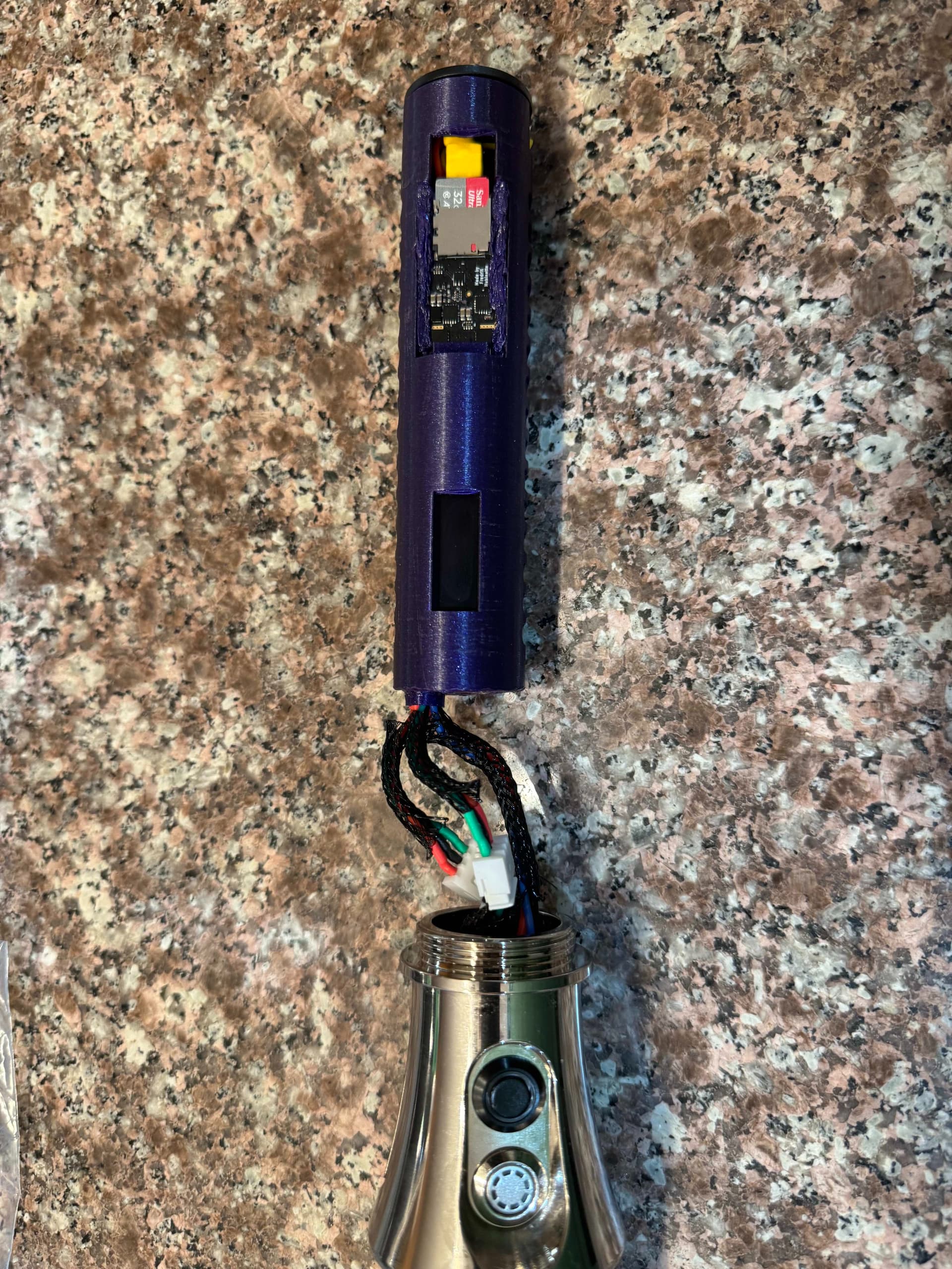
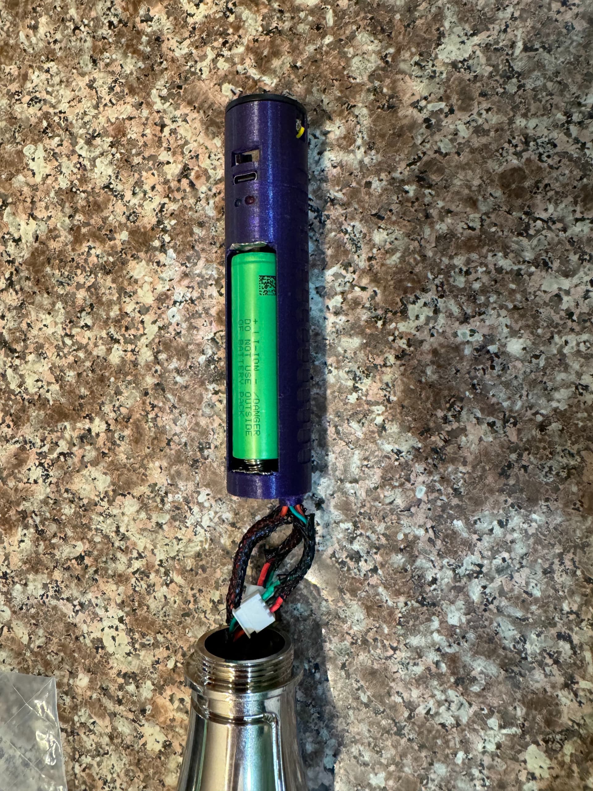
Released the board from the chassis. No visual signs of damage, but it gets warm to touch. I’ve just tested few pins. No short on the 5v pin. There is 31ohm resistance between the 3.3v and the ground. When powered, 3.3v pins produce around 1.5v. I have the Bluetooth and OLED screens still soldered to the 3.3v pin. The charger outputs 1.7v when battery is removed.
That doesn’t sound good.
It sounds like the CPU has fried and is pulling down all the voltages because it’s become a short inside somewhere.
I’ll be ordering new one. Just want to understand if I did something wrong with the wiring that puts additional load on the board and fried it, or it was just a bad apple. I’ve wired both OLED display and the Bluetooth board to the 3.3v pin and the accent LED with the resistor to the “SD Power (11)”, is that correct, or I should have wired them the other way around? The wiring for bluetooth is bit inconsistent here, the diagram shows v3.3 pin to be used, but the pinout mentioned SD Power to be used.
https://drive.google.com/file/d/1vn9vRk-CNZSUHL4xm_hHwS6UgkfKXdO2/view
“SD Power” is also 3.3v, but controllable. It’s weird to use it for accent LEDs.
As long as your accent LED doesn’t draw too much current, this should be fine.
One risk of connecting things to the 3.3v rails is that if you somehow manage to short it to USB or battery power, then you would fairly quickly break things, but obviously I don’t know if that is what happened or not.
What does it mean to be “controllable”? Sorry, wasn’t clear if it is best to connect those devices and the accent LEDs to the 3.3v or SD Power?
I’m confident that there was no short. Things are pretty tight there, and there was no movement. Also tested afterwards too.
Are the Proffieboards ok to stay on for 2 hours? Also, do your boards get warm they they are on?
It means that the board has the ability to turn it off.
It doesn’t generally do that though, which means that right now, connecting things to 3.3v and SD_POWER is the same thing. However, I may change that in the future, and then your LED will turn off unexpectedly, so don’t use SD_POWER unless you know what you’re doing.
Yes, I’ve had some on for very long times
Generally no. It is possible for a board to get slightly warm while blades and sound is on, but it should be fairly low temperatures generally speaking.
If you’re running Bluetooth, did you fit a capacitor between the 3.3 volt and the ground pad? I’ve never quite understood the science, but apparently not having one with a Bluetooth module can cause issues. That said, if your board is getting hot, it does indeed suggest a short somewhere.
Some BT modules draw a lot right when they turn on. This can cause the 3.3v supply to sag (meaning that the voltage drops below 3.3 volts) which can in turn cause things that rely on the 3.3v supply (like the CPU, SD card and motion chip) to crash. Capacitors acts like little batteries that help power through the spike in power drain.
It shouldn’t cause anything to fry though. (Although weirder things has happened.)
No, I didn’t do any of those. Followed the instructions here below. Page 18. Unit: FSC-BT630.
https://drive.google.com/file/d/1vn9vRk-CNZSUHL4xm_hHwS6UgkfKXdO2/view
What is the board manufacturing process? Do vendors order themselves and have control over individual components?
Yes, I provide testing hardware to the manufacturers, and I try to tell them which components they shouldn’t mess with, but I cannot guarantee much, ultimately, a lot is up to the manufacturers.
More than that, the components themselves sometimes have high variance in quality, which is pretty much out of the board makers hands.
Are there manufacturers that you know produce quality boards?
I have seen boards from KR sabers, Artekit and Electronics123, and they seem fairly solid. Others might be just as good, but it’s harder to say.
Ordered two from Electronics123. Can’t wait…
![]() I installed the new board used it for a two weeks. Charged it about 4-5 times. Then almost the same thing happened again. After I disconnected the board I felt that it is pretty hot. The board would turn on with initial sound but then would stop responding to any commands. The OLED would also not turn on. I kept it there turned off, and suddenly it turns on… Want to understand what is going on. Does the charge go into some over-voltage mode? Why does it start working after 5 minutes?
I installed the new board used it for a two weeks. Charged it about 4-5 times. Then almost the same thing happened again. After I disconnected the board I felt that it is pretty hot. The board would turn on with initial sound but then would stop responding to any commands. The OLED would also not turn on. I kept it there turned off, and suddenly it turns on… Want to understand what is going on. Does the charge go into some over-voltage mode? Why does it start working after 5 minutes?
My guess is that the 3.3v regulator is overheating. Once it cools off sufficiently, it would try again.
The question then would be; what is drawing so much 3.3v power? The CPU? The BT board? The OLED? The SD card? Something else? What is actually getting warm?
One possibility is a short inside the CPU. This can happen because of static electricity, shorts, or overloading some of the pins.
Possible. There is BT + OLED display + 2 LEDs with resistor connected to the 3.3v pin. Do you think that’s too much?
Should I use another 5v to 3.3v converter so that it doesnt’t put that much strain on the board?
The board works for 30 seconds, then gets into reboot loop. When it cools off it starts working again.
I’ll check it more tomorrow. How can I figure out what exactly draws the power?
How much continuous load can the board sustain on the 3.3v?
If the LEDs are standard 20mA, this should be fine.
However, there could be something wrong with one of the components causing it to draw a lot more. (Which is why I was asking what gets warm.)
If you wanted to reduce the load a bit, just power the two LEDs directly from BATT+, and use slightly higher value resistors to prevent giving the LEDs too much current.