Is there any doc with the pinout on the 2x20 contacts for the Proffiboard V3 pogo pin adapter? I’m making a rig, but want to do a custom connection to a dedicated blaster testing station, that includes pins for different displays (dual I2C plus one SPI). But need the pinout and I don’t know how to read the KiCAD files.
Currently no.
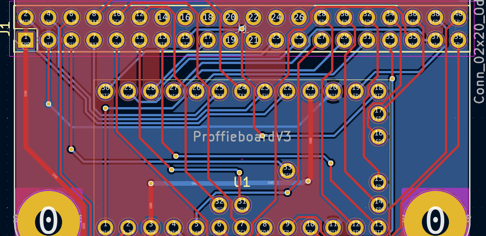
I could probably make one.
Reading kicad files is fairly easy though, you just open them up in kicad and look at them.
@baldusi Kicad is free, so you would likely need to install it. I have the files because I made my own test bed, so I could post a screenshot.
@profezzorn prof, I noticed when I made mine, one of the pins is mislabeled on the test rig files, in a way. One is labeled “Data5” on the 20pin and the proffie board, but it is actually SD power.
Thank You. I will try to make something more readable and share it.
@profezzorn I’m reading that the 0.1" pitch cables can only pass between 1 and 3A per pin. I’ve noticed that you only mapped a single pin from BATT- and may be I could use GND. But it seems awfully little current capacity if I want to run a full sample blade.
And if the board consumes 2/3A plus the blades, isn’t it too little current capacity? Should I wire a few extra cables to that?
The pogo pins aren’t good for more than 3A anyways.
The test bed isn’t really for running a full blade.
I do have a way to test a full blade, but I use a direct connection to the battery/power supply when I do that.
AFAIK, the only way to get sufficient amount of current through the board to drive a full blade reliably is soldering.
2 Likes