You chose quite the interesting place to jump in.
2 Likes
yeah I know its far out of my league 
I changed the define to serial flash but while uploading an error appeared
Arduino: 1.8.16 (Mac OS X), TD: 1.55, Board: “Teensy 3.2 / 3.1, MTP Disk (Experimental), 96 MHz (overclock), Faster, German (Mac)”
ProffieOS: In function ‘void setup()’:
ProffieOS:1734: error: ‘serialFlashSelectPin’ was not declared in this scope
SerialFlashChip::begin(serialFlashSelectPin);
^
Mehrere Bibliotheken wurden für “SD.h” gefunden
Benutzt: /Applications/Teensyduino.app/Contents/Java/hardware/teensy/avr/libraries/SD
Nicht benutzt: /Applications/Teensyduino.app/Contents/Java/libraries/SD
‘serialFlashSelectPin’ was not declared in this scope
Dieser Bericht wäre detaillierter, wenn die Option
“Ausführliche Ausgabe während der Kompilierung”
in Datei → Voreinstellungen aktiviert wäre.
Need to see your config file to be able to help.
also I got some problems with the LEDS and the wiring do you got some wiring diagram or something like this?
these are the leds that I use they only got 3 pins
Your config file includes “v3_config.h”. This base config file is for a teensysaber v3 board, which does not have any serial flash on it, so it doesn’t define a pin for activating the serialflash. Try using “v1_config.h” instead, which is set up for teensy+prop shield.
1 Like
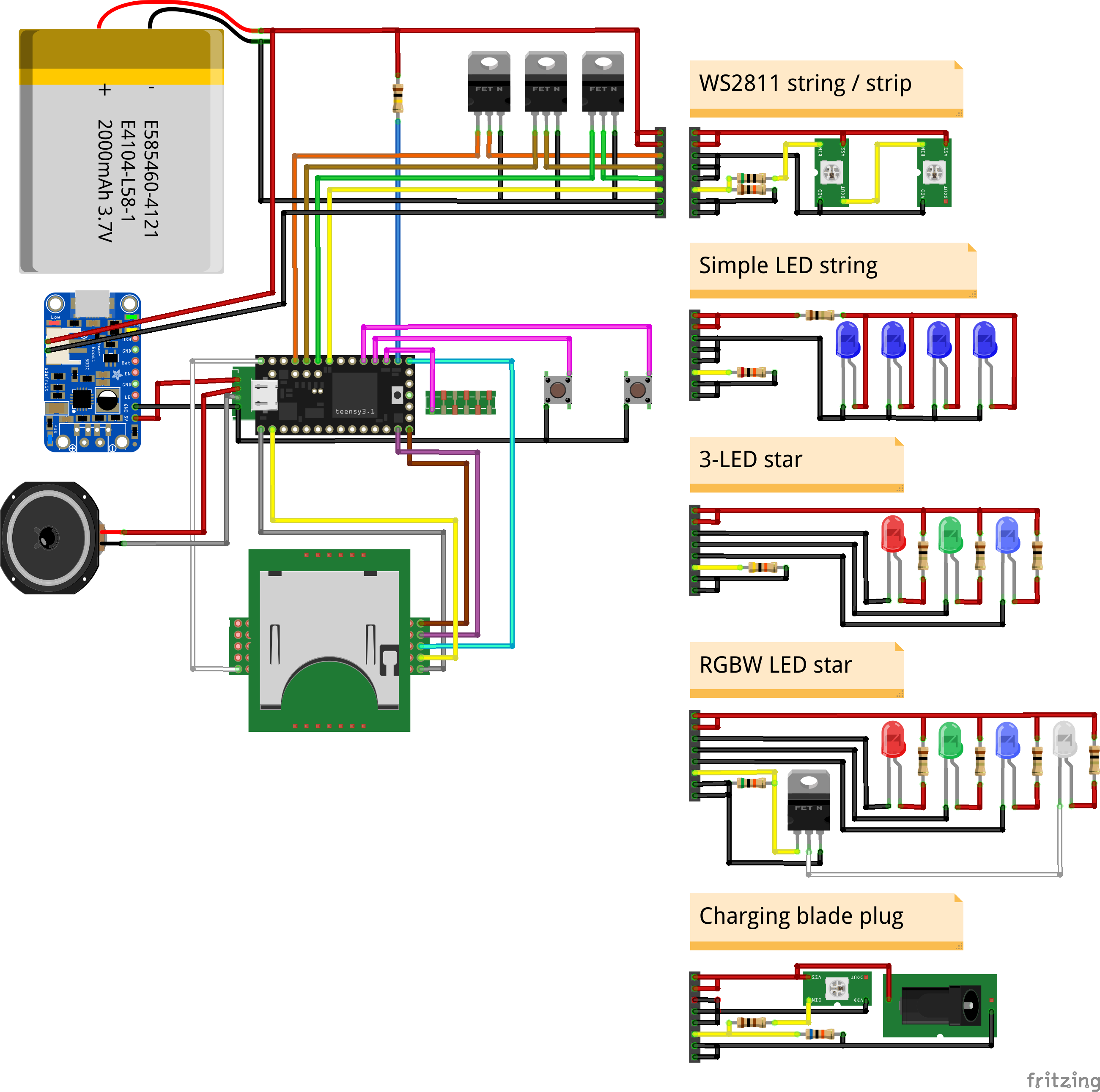
I have these two diagrams. The first one is not very well drawn, but it is meant for a Teensy + prop shield with an 8-pin blade connector. It can be simplified a fair amount, as you can potentially get rid of the booster, FETs, and all but the first blade. Also, the blade connector will probably be a 3-wire pogo pin connector.
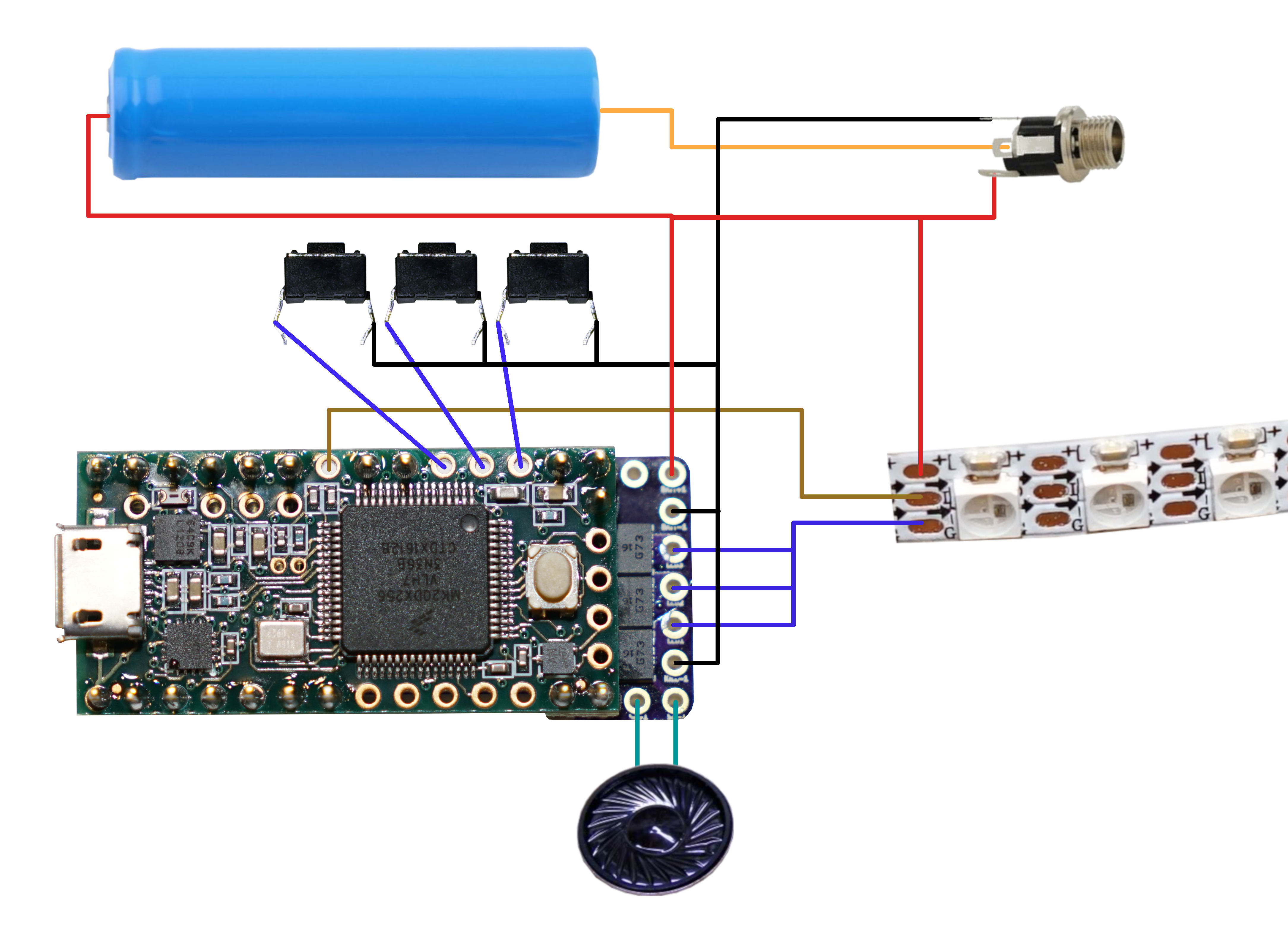
This second diagram is much simpler, and doesn’t show any kind of blade connector at all. This diagram shows a teensysaber v2 board. In your build, the blue wires will either connect directly to the black wire, or go through a FET controlled by pin 21 on the teensy.
2 Likes
ah ok then I will use the v1 file!
I thought the leds plug directly on the prop shield?
this is the circus that I found online from the I like to make stuff yt video.
so I need to solder everything on the teensy 3.2
so I changed the file to v1 then this errors came
Arduino: 1.8.16 (Mac OS X), TD: 1.55, Board: “Teensy 3.2 / 3.1, MTP Disk (Experimental), 96 MHz (overclock), Faster, German (Mac)”
In file included from /Volumes/Somnium Craft/Teensy/ProffieOS/ProffieOS.ino:348:0:
/Volumes/Somnium Craft/Teensy/ProffieOS/common/battery_monitor.h: In member function ‘float BatteryMonitor::battery_now()’:
/Volumes/Somnium Craft/Teensy/ProffieOS/common/battery_monitor.h:135:20: error: ‘BATTERY_PULLUP_OHMS’ was not declared in this scope
float pullup = BATTERY_PULLUP_OHMS; // External pullup
^
Mehrere Bibliotheken wurden für “SD.h” gefunden
Benutzt: /Applications/Teensyduino.app/Contents/Java/hardware/teensy/avr/libraries/SD
Nicht benutzt: /Applications/Teensyduino.app/Contents/Java/libraries/SD
Fehler beim Kompilieren für das Board Teensy 3.2 / 3.1.
Dieser Bericht wäre detaillierter, wenn die Option
“Ausführliche Ausgabe während der Kompilierung”
in Datei → Voreinstellungen aktiviert wäre.
The prop shield LED port is meant for apa102/dotstar pixels.
It could be used for WS281* pixels too, but the port is time-shared with the serialflash chip. For dotstar pixels that not much of a problem, because you can pause a dotstar stream at any point and continue later. WS281* pixels don’t work that way, so it causes problems. Also, driving a whole LED strip through the board itself might make the board warm up, which might not be what you want. The prop shield has no way to control the power to the LED strip, so running the power through the board doesn’t gain you anything.
1 Like
The v1 config file requires an external resistor to measure battery voltage.
You can see it next to the three FETs in the first circuit diagram I showed.
A 15k to 47k resistor is recommended. ProffieOS wants to know what resistor
size you used, so you need to put something like:
#define BATTERY_PULLUP_OHMS 22000
in your config file. (Assuming you used a 22k resistor)
1 Like
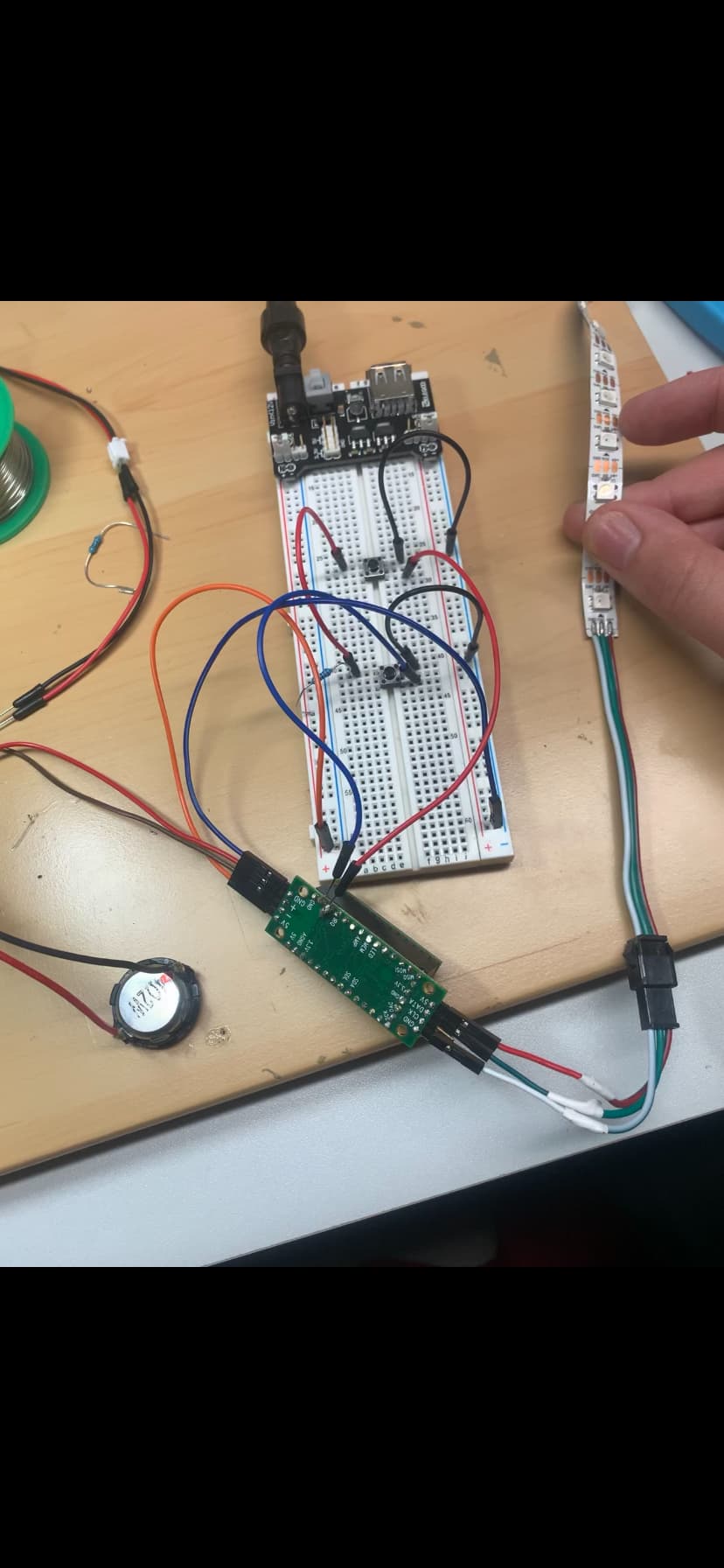
if its not necessary the I will plug the led strip directly to the 5V line. and only the data cable on the teensy (not the prop shield If I get it right?)
I only have 10k or 100k resistors maybe set 2 10K in line?
Where do you get 5v from? It’s usually best to drive the pixels directly from the battery. (~3.7 volts)
Two 10k resistors will work. A single 10k might work fine too.
correct
It may be a good idea to have a 470ohm resistor between the teensy and the data line, but yes, you have that right. If you don’t have a FET for turning on the power to the LEDs, then the resistor might not be needed either.
If you’re going to use a pogo pin connector, then I recommend a 470 ohm resistor on both sides of the connector (in series, on the data line) to protect both the teensy and the pixel strips from accidental shorts.
good I will try it.
i see that there is a extra board on the 2nd pic from you?
but ground aswell to the teensy or to the battery?
The second board in that picture is a TeensySaber V2 board:
https://fredrik.hubbe.net/lightsaber/v2/
Since the neopixels draw a fair amount of power, you probably want to wire the + and - from the neopixels more or less directly to the battery. You probably want a kill switch and/or a charge port in between somewhere though.
Ideally you also want a FET in there so that ProffieOS can cut the power to the pixels when not in use. The reason for this is that neopixels tends to draw ~1mA each when even when showing nothing. So if you have ~200 pixels in your blade, you will have ~200mA of battery draw even when the saber is off. This reduces the standby time fairly significantly.
Now, Teensys aren’t great at power management, at least not when used with ProffieOS, so the teensy will draw something like ~30mA in standby as well. Having a kill switch that turns of the power to both the teensy and the blade means that you gain essentially infinite standby time, and you don’t really need that FET anymore, because you can just cut all the power by using the switch.
Without no switch and no FET, standby time would be something like maybe 10 hours. (Meaning that the battery would be half empty after 5 hours of doing nothing.)
my plan was to make a kill switch and on the blade two momentary buttons for on/off blade and color changing. maybe its a good idea that im making a drawing of my planed circuit and send it in here for checking
1 Like
Two buttons sounds good. Depending on what prop file you use, your buttons will be able to do many more things than just on/off and color change. Posting a circuit diagram might be a good idea, but beware that it’s easy to miss minor details, so even if people say that everything looks good, don’t assume that it’s infallible…
yeah I believe that but for the start ist it difficult enough for me