The Proffieboard is such an amazing system, and the more I learn about it, the more I’m discovering lots of little-known features that have the potential to make certain installs much simpler or better-featured. For example the ability to wire switches so that they short to battery positive rather than ground with nothing more than a tweak of the code can save valuable wire space in tight builds. Indeed I did an install recently in which I would have liked two-button operation, but the number of rings on the removable chassis section meant I didn’t have enough lines for Main, Aux and Ground, so I had to ditch the Aux and go to one-button operation. But had I known about this little feature, I could have ditched the ground and wired the switches to the Batt+ at the back of the blade connector, thus keeping two switch lines.
So in my constant quest to reduce the amount of wiring I need to cram into my builds, and always wanting my toolbox to give me as many build options as possible, I’m curious whether taking other liberties like the one in the diagram below is OK…
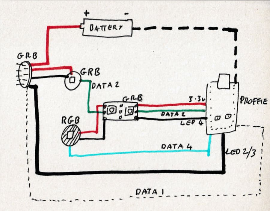
Basically I’m wondering just how much I can cross-connect LED power pads and data lines. So let’s take a hypothetical scenario loosely based on a build I did recently. The basic scenario is:
-
Three accent LEDs with dataline wired in series through all of them and coded as sub-blades. But of those three accent LEDs, numbers 1 and 2 are powered off one LED power pad (let’s say LED 4) and the 3.3 volt positive pad, but the last LED is powered from splits of the main blade LED pads 2 and 3 with positive hard off the battery.
-
A fourth accent LED is also fitted, but this must have its own data line as its colour order is RGB, not GRB. But for wire management reasons, it’s easiest to power that fourth LED off the same positive and negative as the first two accent LEDs in the other array, i.e. LED 4 and 3.3 volts.
Obviously I would need to use the SHARED_POWER_PINS define, but are there any other objections to this scheme seemingly convoluted, but more wire-efficient, scheme?
My own thoughts are that the LED power pads and data line cross-connections would be fine, but I think the mismatch of positives (3.3 volt versus battery positive) on the same LED array might be an issue, resulting in the various components trying to balance their voltages via the data line, which in turn could cause lighting style interruptions on those LEDs, or worse.
In this instance I could of course wire the LED behind the blade connector using data 1 and coding as a sub-blade before going on to the main blade, but that would prevent another little-known feature I want to use which is blade plug charging as it would mess up the Blade ID process.
So I’d value the thoughts of the clever folk here to help me figure out where the line is between unconventional installs and unworkable ones. How bad is this hypothetical scheme? Or is it all, in fact, completely fine?
Thoughts welcome. Thanks in advance.
![]()