I want two, round momentary switches for a saberforge hilt i bought.
I figured it would be easy enough but the diagrams for proffie show three connections to the board for the primary and two for the aux.
I may be overthinking it, but i cant get past the notion that it may not work, and i dont want to strain or fry my board on a half assed job. So i hope to learn from my betters.
Any tips?
This looks correct, assuming you have a 6-pole “dumb” common anode RGB switch. If your switch is ne-pixel then it’d be a bit different, but I see nothing wrong with what you have here given what you described.
Im embarrassed to not have mentioned it sooner, yes it’ll be for neopixel.
Both buttons have four poles. And while I’ve made single buttons work, having an auxiliary is a new concept for me.
Is the switch neopixel though? or is it a normal RGB switch?
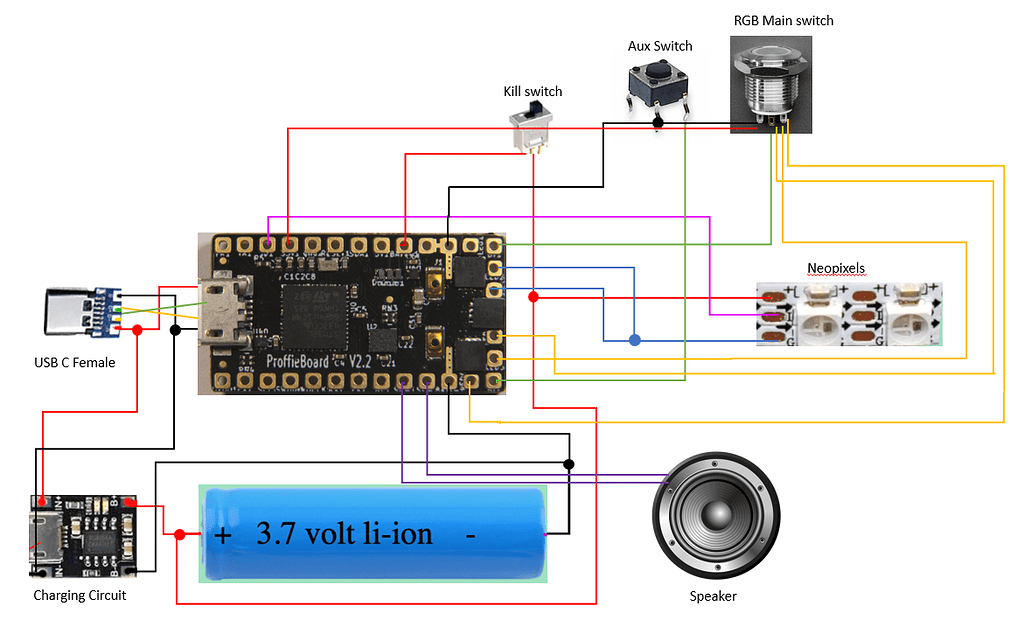
The auxiliary switch has 4 poles coming off it, but it only has two pins in reality (if you’ll notice, those pins kind of follow a direction, parallel to the other set. The ones that follow the same line are actually the same pin)
The way you have it depicted right now where you’ve got one wire going to each side of the aux switch is correct (intentionally or not). One side goes to ground, the other to the Button2 (AUX) pad on the proffieboard, all that checks out. Whenever you press the switch, those two pads get connected together (“shorted” together), and the board detects a press.
For the main switch, you’re showing it setup as a “dumb” RGB switch. That is, you use a separate LED channel to drive each led channel. For example, LED4 for Red, LED5, for Green, and LED6 for Blue. Then you have a power coming from 3.3v as a “Common Anode” for the switch. It’s important to note you most likely need a resistor on each of those negative LED lines (the ones going to the LED pads on the board), or else you’ll fry the internal LEDs. LED aside, it also has the normal pins for a switch, one goes to ground and the other to Button1 (POW), again, this checks out (though the image doesn’t match)
Given you said both buttons have 4 poles, my best guess is that either that main RGB button is actually single color (in which the pins would be LED GND, Switch A, Switch B, and LED+), or it’s set up something like 5V, GND, Data, and Switch, and simply doesn’t have a data out to chain neopixels.
If it’s is in fact a neopixel, then you’d wire up 5V (might just be labeled power or something) to the 5V pad on the proffieboard or BATT+, GND to GND, Data to Data2 (or some other free data pin on the board), and the switch pin to Button1.
The reason that’s weird to me is that the GND for the neopixel and the ground for the switch isn’t separated, which means you couldn’t turn the neopixel off using an LED pad… the absence of a Data out also seems odd…
(It’s also worth noting switches don’t actually have a positive and negative, they just connect two things together, so when I’m giving them names like GND or whatever they’re kind of just labels put on for the sake of conformity or consistency. That’s why I initially describe it as Switch A and Switch B, being the two pins of the switch, polarity agnostic)
If you have two common-anode switches, you’re probably best off powering them in parallel.
You won’t be able to give them different styles and control their colors individually, but do you actually need that?
@Profezzorn: The basic V3.9 config would send Free 2 and Free 3 to power illuminated switches, each with a resistor and a CreeXPE2WhiteTemplate line in the blade config. If I’m interpreting your comment correctly, you could run Free 3 to both switches and have 1 line with a CreeXPE2WhiteTemplate in blade config? Could they be wired in parallel after the resistor (only needing 1)?
Further, is the selection of the Free 1,2,3 pins because they use PWM instead of the WS28X protocol? Would that mean you could use an LED pin as the data line–I believe you alluded to that on another post… or am I completely misunderstanding the PWM checkbox on the table? (it’s the latter, isn’t it).
Or would it be B+ to one pole, and and an LED pin going to B- and GND?
“common anode” means an RGB LED with four pins, one of which is the shared anode (+), then one for R, one for G and one for B. In the V3 configurator, this is called an “RGB Switch”.
It’s technically possible to use LED4,5,6 to drive one RGB switch and use Free 1/2/3 to drive another, but it’s entirely possible that doing that will cause the colors to not match very well, so I was thinking that you can use LED 4/5/6 to drive both switches.
The plain “illuminated switch” does have four pins, but it’s not an neopixel setup, it’s just a single LED inside the button. If that’s what you have, you can drive one button with LED5 and the other with LED6. (Or use Free1/2)
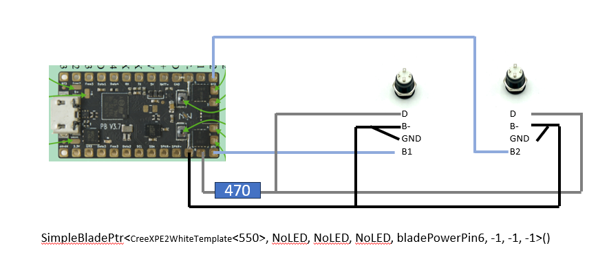
If you have buttons that speak WS2811 protocol, then none of the stuff above applies. The pin names you gave (D, B-, GND, B1) doesn’t really make sense for neopixels though.
Your circuit diagram is confused in a couple of ways:
- If your buttons use regular LEDs, then 470 ohm is too much. Usually you want 60-150 ohms, but it depends on the characteristics (and color) of the LED.
- LED6 should be hooked up to the negative side of the diode, not the positive side.
- There is no + provided to the LED.
If these are standard illuminated (single-color) buttons, then just use the V3 configurator and select two “illuminated” buttons to see how it should be hooked up.
Free1/2/3 can speak either PWM or WS2811, depending on how you configure your blades.
The LED1-6 pads don’t make good WS281X data lines. It is theoretically possible, but…
- I’m not sure if the FETs would switch fast enough
- It would require pullup resistors
- All other pins are better at it.

What about instead, i use an lgt button board with a charging port? How would i wire that?
The charge port + and - would go straight to the battery.
The switch pins would be wired as normal. They’re on a PCB but they’re still the same pins, and should be labeled on the PCB.
NOTE: The LGT sabers take a 5V input from typical phone chargers, this will FRY the proffieboard (best case it simply won’t work)!! If you use an LGT recharge port you MUST use a proper lithium ion battery charger like this one!
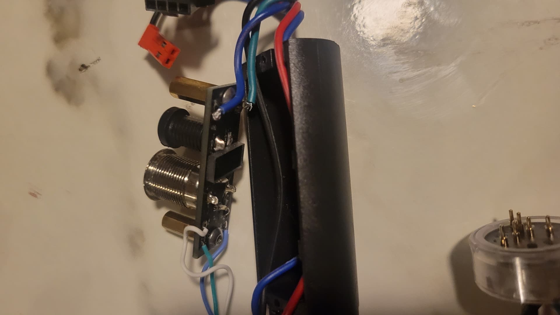
I have a saber with this kind of setup, but I’m having a hard time reverse engineering it. None of it makes any sense to me. The most I’ve done is Pixel GHv3
So, that button itself is no different than any other 4 prong button, (take a look at the interactive wiring diagram and configuration generator or the proffie v2.2 version) and the charge port just has positive and negative to the battery.
If you can get a clear picture of the board with labels can maybe explain what each pad is for, but they just directly connect to a pin on the charge port or button, so it’s the same as if you were wiring them without a PCB at all.