Hi everyone!
I’ve posted a few times with questions, but this is my first update on my build. I’m making progress but there is so much I’m learning all at once it is going slow. I’m building a V3.9 Proffie saber using an 89Sabers Fallen Order V3/V4 hilt and a Tritium quad pixel blade.
I just finished building the quad blade. The 1" tube that came in the kit was just a little too big–and my efforts to shave it down were not the most successful… so I’ll need to rebuild the blade for cosmetic reasons, but for now, it’s working and I’m testing it using my first hilt that came with a pre-installed Proffie V2.2 board. It took some time to get the blade array configuration working–but I successfully lit up the blade with four different color stripes… so I’m pretty happy about that. The 2.2 board is a bit slow when lighting up the blade–and I’m not sure its getting enough power–but I will solve those issues with the V3.9… I soldered on a 33k resistor for blade-id, but I haven’t figured out how to make that work yet–and I can’t use the serial monitor for testing until I finish my new install. I might be able to code up different blade arrays that will let me know if it’s working… but that’s for later. (Side question–if anyone is reading this… has anyone confirmed if the Shtokworx V3 10 pogo connector can drive a quad blade with ~500 LEDs? I was able to track down the 11 pogo connectors at TCSS–but I already have a 10 pogo connector).
For my new install, I’m 3d printing a custom chassis that will have an exposed crystal chamber with a few other features I find lacking in the pre-installed V2.2 I purchased: i.e. a kill switch accessible from the pommel, the ability to charge without removing the battery, and the ability to plug in a USB cable without removing the chassis so I can use the serial monitor for testing. I’m learning 3d printing at the same time, so it’s slow going. My first chassis design did not have enough space to run wires–or had corners that were too sharp to route through-- (everything looks so much bigger in TinkerCad) but I think my current design will work once I get a successful print.
While waiting to get a good print for the main chassis, I’m working on the crystal chamber and trying to get the buttons to connect in the neck (I might have started with a different hilt if I had known how difficult that part would be). I printed the crystal chamber in gold PETG and have a quartz crystal to start with, which I will light up with a 20 pixel round LED. I’ve also designed it so I can change out the crystal–I have a glass D20 that I’m contemplating putting into it to make it “more me.”
Thank you all for the help that has gotten me this far… all the direct help and all the information I’ve been able to glean from this wonderful resource… but I’m sure I’ll be back with more questions–and I’ll post pictures once I get a bit more done.
Update:
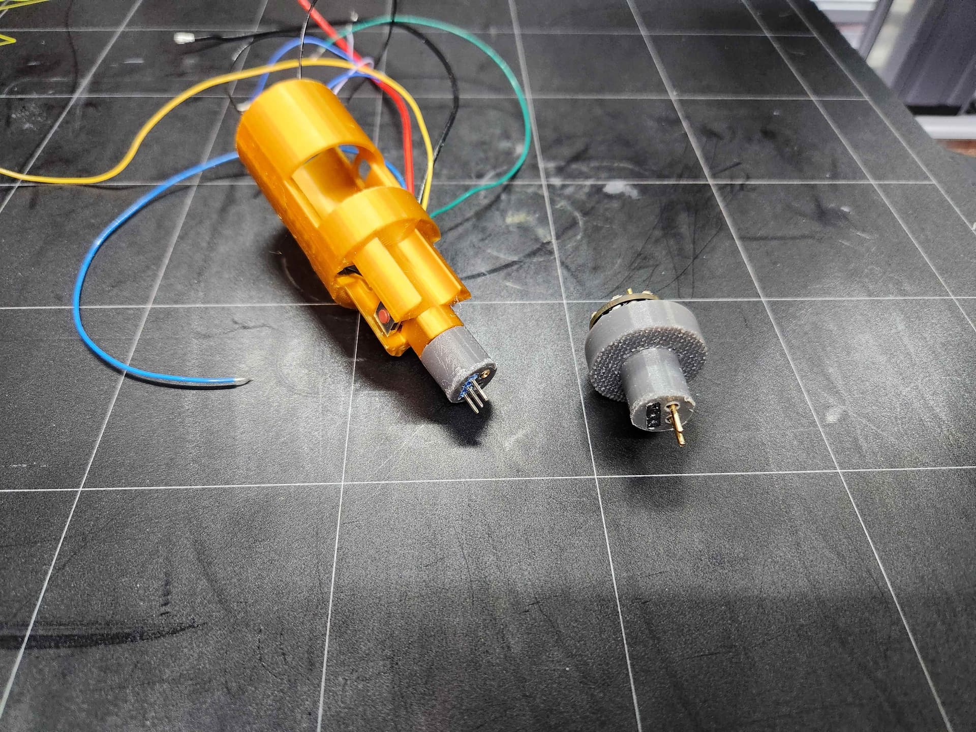
I Finally solved a problem that had been truly vexing me… a thin-neck connector that supports blade-detect and blade-id and has enough power to drive a quad-blade. Here is my custom connector using two 18 awg pins and a 3 pin molex connector (two data and 1 blade detect).
It was a tight fit to get past the neck buttons for the survivor hilt, but finally I got everything to line up and no cross-connections. I’ve also learned that the posts on the High Amp Kill switches we use are compatible with molex connectors. I’m leveraging that to make a removable speaker pod that has a kill switch in the pommel.
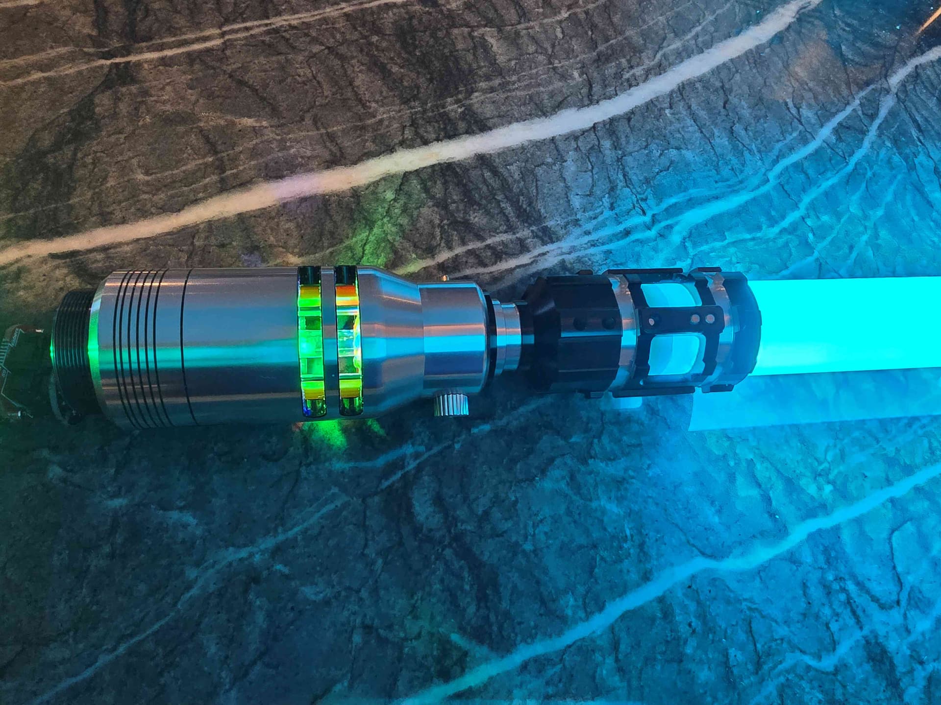
Progress! I must have burned out a pixel ring, but one of them is working and the crystal chamber lights up as does the blade… I’m using sub-blade to control the two pixel rings and the hilt side pcb LEDs (independent).
…now if someone could just tell me the secret to squeezing an inch of 12 cables into an area the size of a postage stamp…
I’m actually having trouble with the 18 awg PTFE wires–they just aren’t sufficiently bendy… but I think the real rookie mistake was using waterproof solder seal butt connectors on my wire splices. it seemed like a good idea when I read about them, but they just aren’t bendy at all and add so much bigger than they looked in the pictures. Straight up heat shrink tubes would have been better. Lesson learned. I could also use more 30awg–and maybe downgrade the wires on the accept pixels. I don’t think I need 22/24 awg for the LED/batt+ to drive 40 accent pixels.
Thanks all for the advice. Pulling it apart and beginning the rewire. I needed to replace one of the pixel rings anyway. I think I’ll try jeweler pliers on the 18awg wire to make it corkscrew without damaging the insulation…
18 awg wire is always stiff, and it’s almost certainly thicker than you need.
Unless you’re doing a quad-blade 22 AWG is sufficient, although 20 might be slightly better.
If you need bendy wires, silicon coated wires are the best, but they tend to be pretty bulky. Sometimes two thinner wires is better because they bend better though.
26awg would be ideal for that, but 28 awg, or two awg 30 would also work.
Yes, I do have a quad blade–and am making more (160led/m and a COB 240led/m). My current quad blade needs 13 amps. The 4x240 strips will require 15A. The 4x160led strips will actually need more, at 16 amps. I’m wiring it up using power pins 2+3 (18awg) and 6 (24 awg), but only 1 Batt+ with an 18awg–which I hope will be okay as it is the upper limit of an 18awg wire per the NPXL manual–but I will likely shorten the blades to get down to 13-14A range (36" vs 1M alone should shave off 1A–but I’m learning all of this as I go, so I could be wrong).
18awg may still be overkill, but too much copper is always better than too little.
There are NO exact limits to how thick a wire needs to be though. It all comes down to how long the wire is and how much power you’re willing to lose in the wire. Ultimately, it becomes a question of heat. (Remember, it’s the LEDs that are supposed to glow, not the wires…)
Usually it’s easy to look up the resistance of the wire you have, or approximate it based on standard tables, and then you can calculate exactly how many volts and watts are lost in the wire based on how many amps you’re trying to transmit.