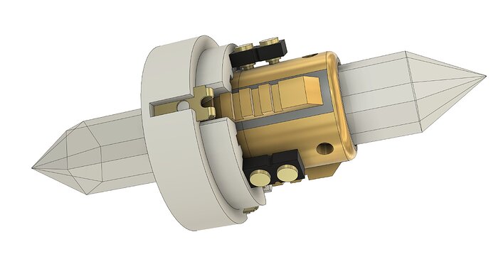
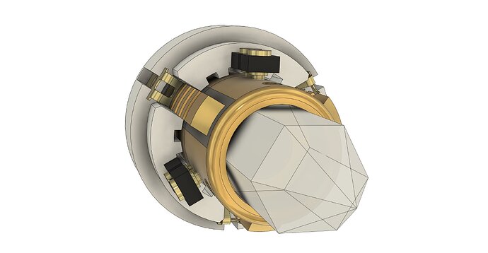
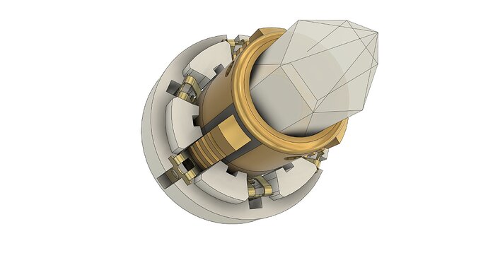
Something like Tangible font selection for proffie?

Ok, so the wiring seems correct.

More questions:

  • Since you used a logic analyzer on it, can you tell me what bytes were actually sent? (And what the baud rate and other settings were?)
  • “monitor serial” might not work if you have DISABLE_DIAGNOSTIC_COMMANDS in your config file. Do you?
  • Can you post your config file so I can see if there is anything else in it that might interfere?
  • Are you sure it’s uploading?
  • What version of ProffieOS do you have?
  • What version of the Arduino-proffieboard plugin do you have?

Hopefully the picture uploads.

I commented out the DISABLE_DIAGNOSTIC_COMMANDS line in my config file, I do get other info like battery level, clashes and so forth.

Am I sure it’s uploading? You mean the program into the Proffieboard? if so, yes, I’m sure.

I’m currently using v7.8

Proffieboard plugin: 3.6.0

Config File:
my_saber_config4.h (32.2 KB)

Your config file doesn’t have RFID_SERIAL in it (which it should) .
It does have ENABLE_SERIAL (which it shouldn’t).
However, you said earlier that you tried doing it the other way, so I’m guessing this is just the latest state.

Assuming this isn’t actually the issue, I’m fairly stumped. It seems like it should work.

I didn’t see the baud rate in the logic analyzer screenshot, is it actually 9600 baud?

DISABLE_DIAGNOSTIC_COMMANDS doesn’t remove all serial monitor output or affect all commands. It just removes commands which are generally not needed once everything has been tested and works right. (This includes the “monitor” command.)

Actually,

My bad, since I’ve been testing with the proffieboard 2.2 I was editing from an older folder instead of editing the config files on the current folder for OS v7.9, silly me.

However, now that I have moved the right config file to the right config folder, I’m getting the following compiler error:

In file included from C:\Users\vicms\Desktop\ProffieOS-v7.8\ProffieOS\ProffieOS.ino:233:
C:\Users\vicms\Desktop\ProffieOS-v7.8\ProffieOS\common\serial.h: In member function ‘virtual void RFIDParser::Loop()’:
C:\Users\vicms\Desktop\ProffieOS-v7.8\ProffieOS\common\serial.h:101:31: error: ‘RFID_Commands’ was not declared in this scope; did you mean ‘RFID_Command’?
101 | for (size_t i = 0; i < NELEM(RFID_Commands); i++) {
| ^~~~~~~~~~~~~
C:\Users\vicms\Desktop\ProffieOS-v7.8\ProffieOS\common\common.h:18:26: note: in definition of macro ‘NELEM’
18 | #define NELEM(X) (sizeof(X)/sizeof((X)[0]))
| ^
exit status 1
Error compiling for board Proffieboard V2.

Here’s the right config file:
my_saber_config4.h (32.1 KB)

And yes, the logic analyzer was set to 9600 baud.

Your config file doesn’t have an RFID_Commands array, should look something like this:

RFID_Command RFID_Commands[] = {
  { 0x0000000C04ULL /* green */, "change_preset", "0" },
  { 0x09003A8CDCULL,             "change_preset", "1" },
};

It specifies what to do when a specific RFID is found.
The RFID_Commands array should be in the CONFIG_PRESETS section.

That did it!

Thank you!

I didn’t think the RFID_Commands were mandatory and I just wanted to test if the proffie was getting the data from the reader, my bad!

That only leaves my other question, a way to know when there is no crystal or when I take it out.
I’ll either use pogo pins as I mentioned before or most probably spring contacts, they might be more suitable for my situation since if you see my attached pictures, the pogo pins are not really design for lateral movement, in this way at least, so I might opt for spring contacts just like the ones I’m already using for signal and power to the crystal neo pixel LEDs.

Let me know if something like this would be enough, in the pictures there are 2 pairs of pogo pins just for redundancy and symmetry.

If I decide to go with spring contacts then it would be only two, one per side.

Seems like it should work.
The code I have for this uses the blade detect functionality.
Are you planning to combine this with blade detect, because if so I will need to cook up something better than what I currently have.

No, not planning on using blade detect.
But I do want a crystal detect.
I want to detect when a crystal is removed and not present, that way maybe I could prevent the ignition, probably play an ignition failed sound and it would also be cool to show something (like a no crystal warning) in the currently in development color LCD.

My idea for the crystals, in addition to what I described above, and beyond just selecting a certain preset, which is already cool by itself, hopefully if possible, is to divide the presets depending on what crystal is inserted, like having one light side crystal that would allow me to cycle only through light side presets, the dark side only through dark side presets, and one master crystal that would allow me to cycle through all of them, basically using them as access keys.

Maybe I’m being too ambitious, but maybe it can be done?

It’s doable, and here is how you do it:

First, add this to your config file:

#ifdef CONFIG_STYLES
int crystal_blade_id;
struct CrystalBladeID {
  float id() { return crystal_blade_id; }
};
#define BLADE_ID_CLASS CrystalBladeId
struct CrystalBladeIDCommand : public CommandParser {
    bool Parse(const char *cmd, const char* arg) override {
       if (!strcmp(cmd, "set_crystal_blade_id") && arg) {
          int new_blade_id = strtol(arg, NULL, 0);
          if (new_blade_id == crystal_blade_id) return true;
          crystal_blade_id = new_blade_id;
          return CommandParser::DoParse("scanid", nullptr);
       }
       return false;
    }
};
CrystalBladeIDCommand crystal_blade_id_command;
#endif

Then in your RFID_Commands you use “set_crystal_blade_id” instead of “change_preset”, like this:

RFID_Command RFID_Commands[] = {
  { 0x0000000C04ULL /* green */, "set_crystal_blade_id", "1" },
  { 0x09003A8CDCULL,             "set_crystal_blade_id", "2" },
};

The numbers you provide to set_crystal_blade_id can technically be anything, but you’ll want to set up your blade array with one entry for each number. So if your RFID_Presets use “1” and “2”, then our blade array would look like this:

BladeConfig blades[] = {
   { 1,  /* blade stuff */,  CONFIGARRAY(green_presets) },
   { 2, /* blade stuff */, CONFIGARRAY(red_presets) },
   { NO_BLADE, /* blade stuff */, CONFIGARRAY(no_blade) },
};
1 Like

That’s Awesome!!

Thank you, I’ll start playing with it!

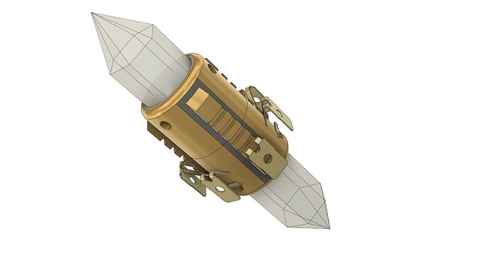
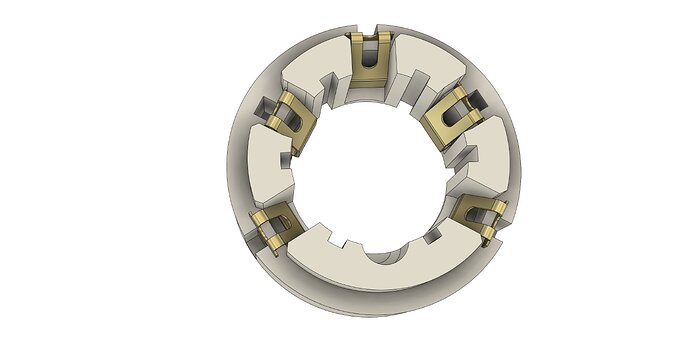
This is how I ended up going with when it comes to the crystal detect contacts.
Spring contacts are more suitable for this application than pogo pins.

Are those two contacts (the ones touching the main body) enough to implement the crystal detect?

1 Like

Yep, one would connect to ground, and the other to the blade detect pin, which could be any GPIO-capable pin on the board.

Hi Vic,

Sorry to necro - did you ever get this working? I am trying to accomplish something similar with crystal detect but am a little out of my depth. Do you mind me asking the part numbers for the contacts you are using above?

Also, a general question for everyone, just to make sure I have it correct - if I wanted to do a crystal detect function without the additional RFID elements, I would just need a resistor attached to the crystal for BladeID to detect that it is present, correct?

Hey Nightwing,

Sure, no problem, here:

https://www.digikey.com/en/products/detail/harwin-inc/S1741-46R/2264458?s=N4IgTCBcDaIMoEYDsAWBBaFA2ASiAugL5A

You can make a crystal detect just with a contact, it will “know” if it has a crystal in or not, what it won’t know is if it’s a specific one, for that you’d need a way to ID it, and one of the best ways is to use a RFID reader.

It’s also possible to use a resistor to identify the crystal, similar to how Blade ID works.

Many thanks for that Vic!

So if I wanted to build a removable crystal module with an inset pixel accent, I’m wondering how many contacts I would need. Pos, GND, and Data for the LED at a minimum, and then another pin for BladeID? Or could that be handled through the data line? I guess this is more a question for you Prof!

Apologies for the noob questions

It is possible to do with three pins, but I would do four if possible, since that simplifies things. The fourth one can be used for blade detect, blade ID, or both, depend in how it’s wired.