I’m building my first Proffieboard v3 lightsaber, and I’m struggling to find a way to do what I’d like: safely charge the lightsaber from a wall wart, and power it at the same time (mostly for display purposes). For some context, I’m an EE, and have designed and built many small embedded circuit boards.
One quick question: I’ve seen reference to the “manual.” Is that just this page? Is there anything more detailed? For example, what is JP1 for?
Near as I can tell from various wiring examples (and the configurator tool), the battery is directly connected to the charge port in most installations. This implies you need a Lithium charge controller outside the hilt to safely charge the batteries.
The Proffieboard has an on-board charge controller, but it’s only powered from Vbus, and the docs say it’s for USB charging.
The longer I stare at the v3.9 schematic, the more it seems there’s no good way to safely charge the battery with an external wall wart. What do people use to charge?
I’m considering adding a charge controller to my hilt that can just take 5V in and safely charge the battery.
What do people generally do?
No, what people call “the manual” is a PDF file written by ShtokD, it’s linked from the POD front page (https://pod.hubbe.net/) but it AFAIK, it does not cover the V3 board.
Not really, the design files themselves show how everything is laid out on the board, which can be helpful though.
JP1 was part of my failed attempt to build a low-power-switch control for the board. Unfortunately I made a mistake in the design, and JP1 is useless.
Usually something like this: 1A 3.7v Li-Ion Smart Charger With 2.1mm Plug – Choose Your Adaptor – The Saber Armory
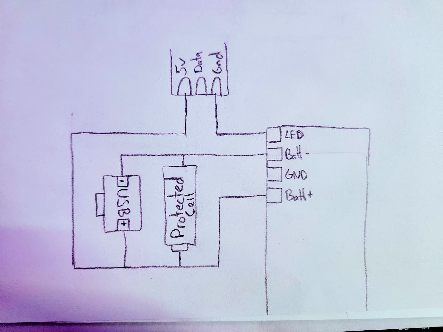
So, it seems like the easiest way to do this is to add a switch which controls if the blade is powered by BATT+ or the 5v input. Also hook up the 5v input to the vbus pad on the board.
This way, the sufficiently powerful 5v input can power the board and the blade, and also allow the battery to charge. The drawback is that the USB connector can become back-powered if you plug in both USB and the 5v input. Also, you could end up trying to drive the blade directly from USB if the switch is in the wrong position. Both should be safe if the USB port is designed correctly, but that’s a pretty big if…
One way to make it a little safer would be to use an USB plug inside the saber instead of connecting to the VUSB pad. That way you would need to unplug the USB plug before plugging the board into your computer.
1 Like
Thanks for the reply, @profezzorn. I guess I’ll just go with the typical wiring then, requiring a smart adapter.
How would you feel about incorporating something like this TI IC into Proffieboard v4? Probably better would be a USB-C connected device that allows bringing the USB-C connector outside the hilt for direct plug-in, but I only did a cursory search for an IC that could be added to the existing design without too much trouble.
Unfortunately, I can’t find a tny breakout board for it (maybe I’ll make one). But I think this IC can give 4A+ from a suitable supply (not sure about the thermal implications of that, maybe one can use the hilt as a heat sink) and safely charge the battery at the same time.
4A is still not enough to power the blade though.
If you want to have a setup where the saber can be on for extended periods of time, like a lamp, then you’re going to need at least 10A.
(Or did I misunderstand what you wanted to do?)
Ah I suppose you’re right. I’m sure there’s still an option out there. Something with USB-C PD, 10A, li-ion charging, and 10 A boost converter.
I think maybe you mean a buck converter to convert something like 3A@20V to 10A@5V? (Fitting a 50W buck converter in a hilt would be a neat trick though.)
I think what you want is a 10A@5v power supply that drives the blade, the board and the battery charger. That means disconnecting the battery from the blade while charging is happening though, otherwise it would over-charge the battery.
It might be possible to use a FET or two to do the disconnect automatically when power is connected.
What I’m imagining is really two possible improvements:
- A 2.1mm external power port for charging and unlimited power
- A USB-C port for charging, unlimited power, and programming
The latter would be ideal, but but would require a complete redesign of the existing board. The former could probably be made as an add-on board.
Both require buck and boost converters, if you want to always supply 5 V to the LEDs (right now, LEDs are supplied directly from Vbatt. I think with a boost converter, you could get longer life out of the battery). You need a buck converter for charging the battery, assuming a minimum supply voltage of 5V (and possibly as high as 20 V in USB PD).
I don’t know if any of the available PD ICs can deliver 10 A @ 5V and charge a single cell, but I wouldn’t be surprised if one existed.
I don’t know how big the external components have to be. I doubt you can fit it all into the existing v3 footprint, but personally I’d be okay with a larger board if it did all that stuff. In my current build, the KR Sabers Thrwan Hunter with eco chassis, I think there’s enough room. Not sure if the master chassis has enough room. I’m not at all sure how to get a USB-C port out of the hilt.
The other thing I can do in the Thrawn Hunter hilt is use it as a heat sink: it has flat sides, perfect for laying a power board against with some thermal paste or foam
If you don’t mind a the blade going off-color when the voltage is low, the answer is no.
If you do mind, the answer is still no, because it’s hard to find a boost converter that is can handle the current while still being small and efficient enough.
1 Like
You probably know best. I guess I’m just being wishful.
It’s been a while since I looked though. Things could have changed. Maybe some sort of GaN thingy would be small and efficient enough?
1 Like
While researching another LED project, I came across the LTM4702, an 8A buck converter in a 6.25mm × 6.25mm × 5.07mm package. I don’t think that’s the solution for light sabers, but it shows what’s possible!
That’s pretty cool. First time I’ve ever seen a buck regulator with an integrated coil!
(Usually the coil is what takes the most space.)
Hopefully someone makes an class-G amplifier chip with I2S input and an integrated coil. That would remove the need for a 5v booster on the board and shrink the proffieboard significantly!
I am interested in this same issue. I want to have the saber be a wall display when otherwise not in use. (I am not an EE) But if you have a protected Cell (PCB that cuts its circuit at over/under charge) Why wouldn’t this work? I have not used a proffieboard yet, I have used ESP boards with LED strips and by running them at under 50%, a 2A USB power supply can run 250LEDs no problem. In the diagram “USB” means just straight 5v power.
- You can’t hook up 5 volt directly to a battery, that will damage the battery.
- Your math seems off. 250 LEDS can draw up to 7.5A, which means that a 2A power supply cannot drive it. Also, there is no USB connector rated for 7.5A
EDIT: I missed the 50% part, but even then it doesn’t quite add up…
EDIT2: some batteries may have protection circuits that will protect them against 5 volts, but I don’t know how you would know that.
Now, if this was 4.2 volts instead of 5 volts, then it should be safe.
Some power supplies have an adjustment resistor, and maybe they can be changed to provide 4.2 volts?
Yeah I think I’m exercising some wishful thinking on the protection circuit. A protection circuit is not a charge IC. Thanks. BTW, this was a great article on protected battery IC tech. The Anatomy of a Protected Battery
So I am already doing this “wall saber decoration” with an ESP8266 and around 250leds. I’m using WLED software which you flash to the board. WLED has a brightness throttle in setup which they put in terms of an amp limiter.

My experience with overdriving USB power supplies with LEDs is that, they just go into protection mode until you take the load off, but yeah it could kill them.
How I have the wall saber setup is with a charge IC like this: https://www.amazon.com/dp/B0BZ3LXQWT
The 5v output goes to the ESP8266 and also to the LED +/-. This is severely amperage deprived though and driving it past 2A causes a shutdown. But at the same time, I think 2A is very bright, I never run it even close to that when on the wall, and I set the limiter to 2A as shown above. Regarding current draw, a single color (RGB) is pulling 33% of the strips max when brightness is at max.
There are two USB ports. I use one for running it on the wall, and the other can be used to charge the battery. The main reason for having that charge/discharge IC though is to boost the battery to 5v for the board and LED data. Oddly, when I power just the ESP8266 it manages to draw the battery down, so if I leave the battery in the saber it will be dead when I take it off the wall.
TLDR - Want to do this with a proffie board (which I dont have yet) and not have the battery be dead, and not have to have the battery on the charger all the time. Also don’t know if Proffie has adjustable brightness or any kind of limiter on the brightness globally.
There are some ways to adjust the brightness on the Proffie.
It can either be done in the config file by using DimBlade, or with edit mode, which can apply dimblade to blades on the fly.
It’s just a percentage though, so you would need to calculate (or measure) the current draw yourself.
1 Like