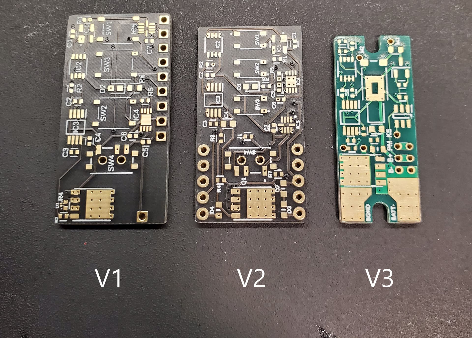
Removed charging system - seemed like a waste of space on the board with Proffieboard V3 coming out.
Power/Auxiliary switches removed from the board - these were limiting the placement in the hilt and were rarely used.
No manual haptic disconnect - the switch was expensive and took up a lot of room on the board.
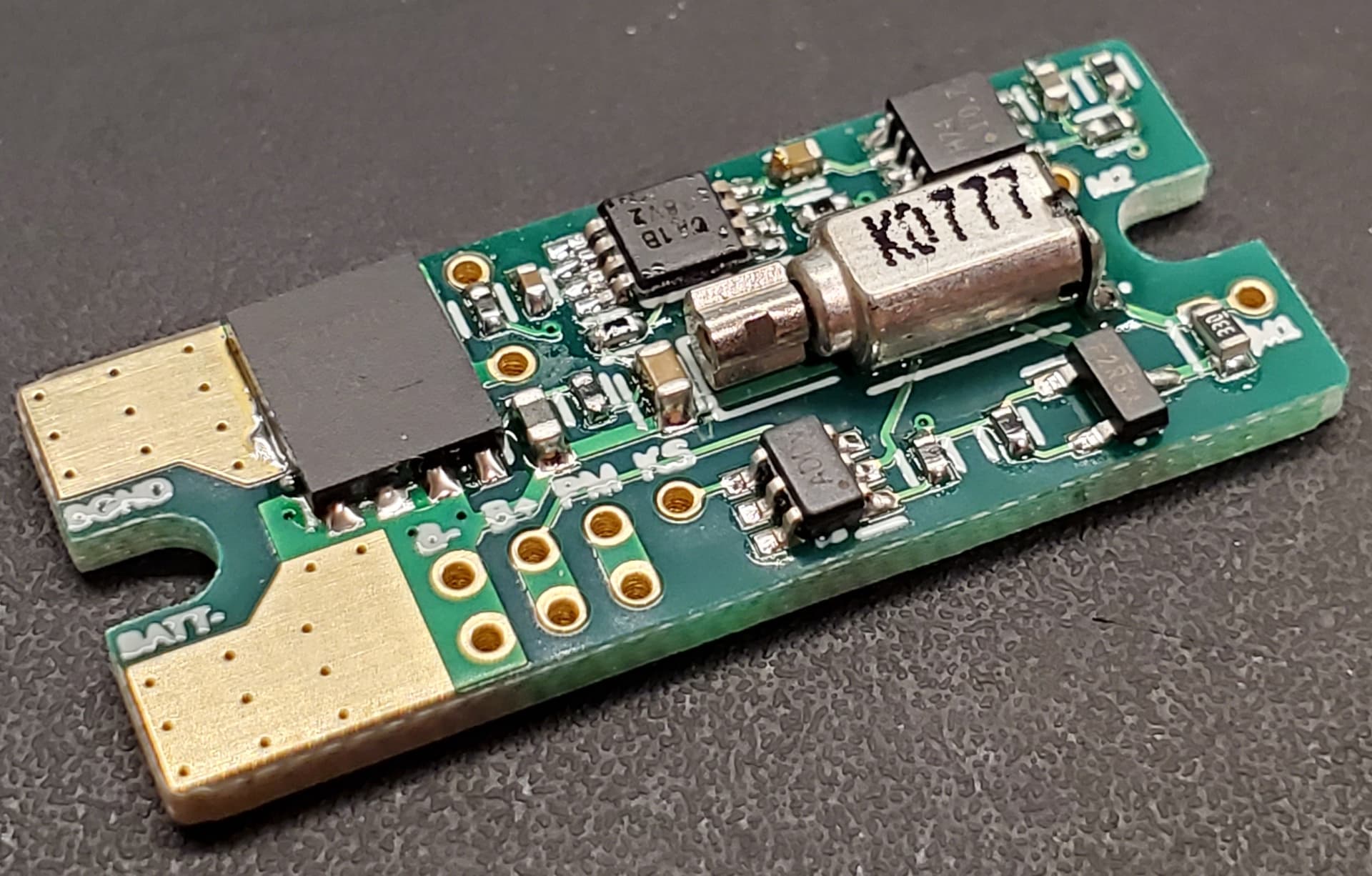
Haptic motor mounted on the board - there are still breakout pads for an external motor wiring. The mosfet can handle up to 4A, so it could be used to switch an LED.
Mosfet based haptic driver - replaces the DRV haptic chip. Now the PWM duty cycle and frequency will not matter.
The board now has much better heat dissipation.
Added mounting slots - sized for a 1-64 button head screw.
FEATURES:
Momentary-based kill switch. The battery can be electrically disconnected from the saber electronics with the push of a momentary button. A high-power FET with extremely low Rds (1.5-2mOhm) allows the user to disconnect the saber electronics from the battery, while handling currents up to 40A. The current consumption of the disconnect system in off mode is only 23uA, which gives a shelf life of about 6 years with a 2 A-hr battery.
Haptic Audio Feedback. The board can take a PWM audio signal and drive a vibration motor to match the sound pattern.
Crystal Focus - set accent LED #2-5-6-7-8 to function “@” for audio PWM signal.
Proffieboard - Speaker + pad has a PWM audio signal.
Golden Harvest - TBD
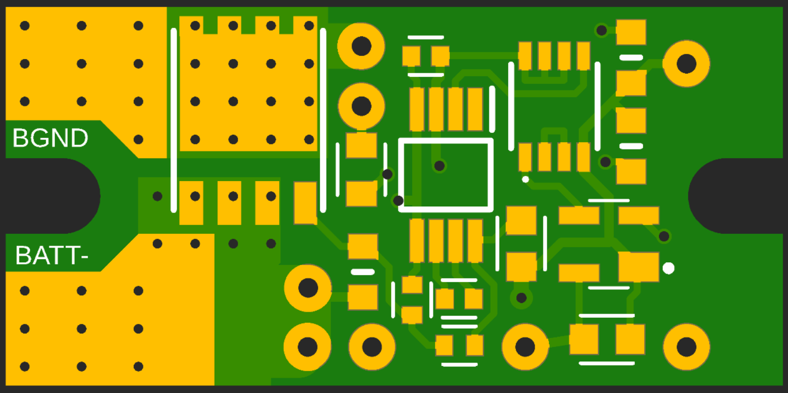
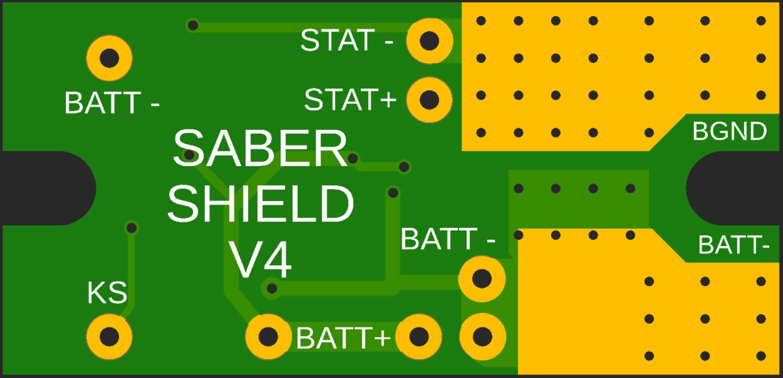
Useful breakouts of board negative, battery negative/positive, and motor connections.
Specifications:
Supply Voltage: 2.2V to 5V
Dimensions: 0.5” x 1.225” x .063” (12.7mm x 31.12mm x 1.6mm)
BILL OF MATERIAL:
Device #
Value / Type
Package
Part #
Qty
C1
4.7uF
0402
CC0402MRX5R6BB475
1
C2
10uF
0402
GRM155R61A106ME11D
1
C3
0.22uF
0402
GCM155R71C224KE02D
1
C4
22uF
0603
GRM188R61A226ME15J
1
D1
ESD Diode
0603
82356050101
1
D2
ESD Array
SOT95P280X145-6N
SP3025-04HTG
1
IC1
D Flip-Flop
SM8
TC7WH74FU,LJ(CT
1
IC2
5V Regulator
SOP65P490X110-8N
REG711EA-5/2K5
1
M1
Vibration Motor
Z30C1T8460001
1
Q1
Mosfet
SOT95P237X112-3N
SI2342DS-T1-GE3
1
Q2
Power FET
Q5B
CSD18509Q5B
1
R1, R4, R5, R8
2k
0402
CR0402-FX-2001GLF
4
R2, R6, R7
100k
0402
CRCW0402100KFKEDC
3
R3
22R
0402
CRCW040222R0JNEDC
1
R9
100R
0402
RMCF0402JT100R
1
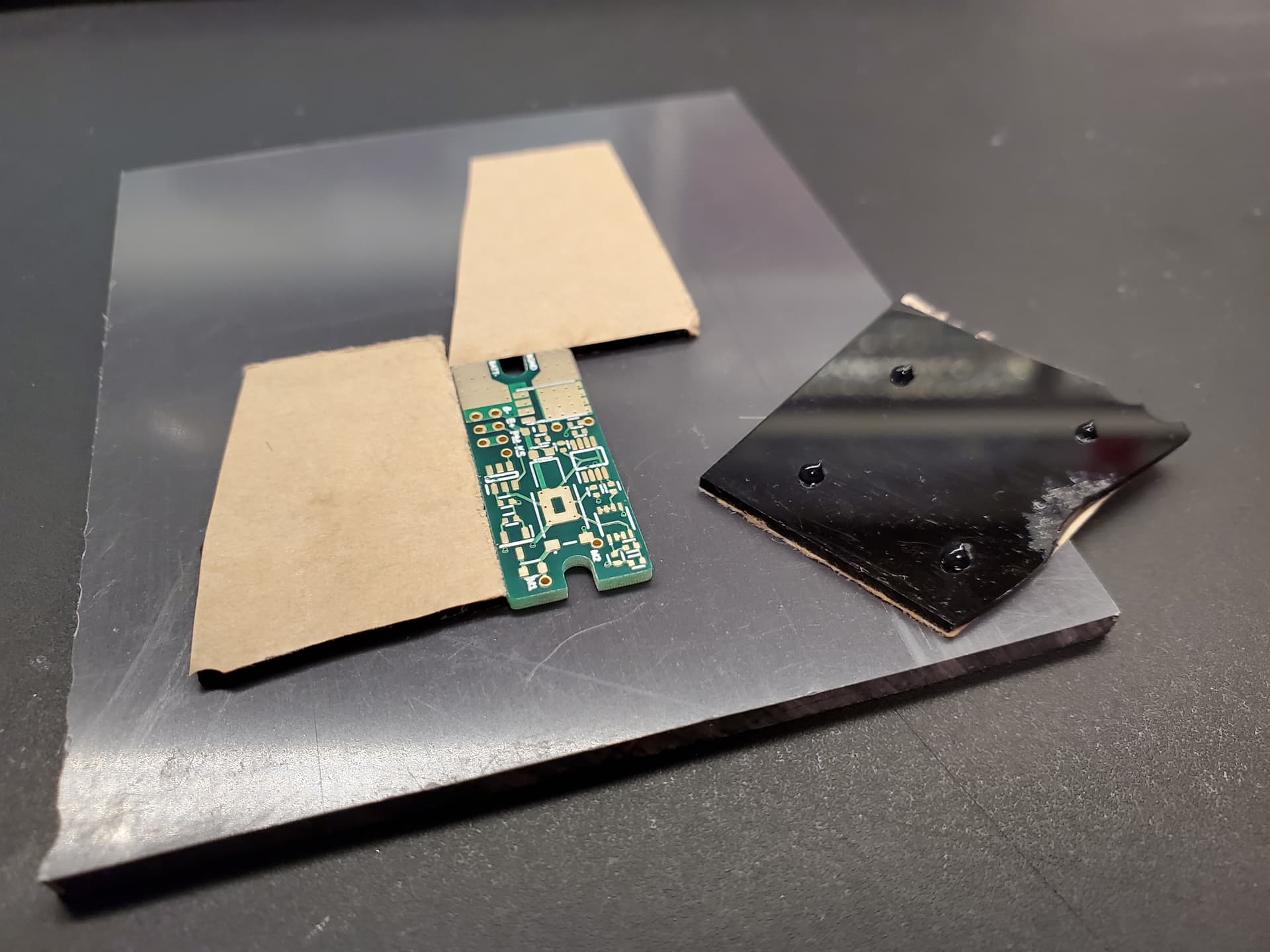
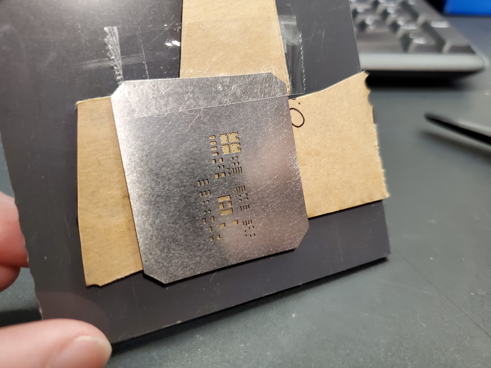
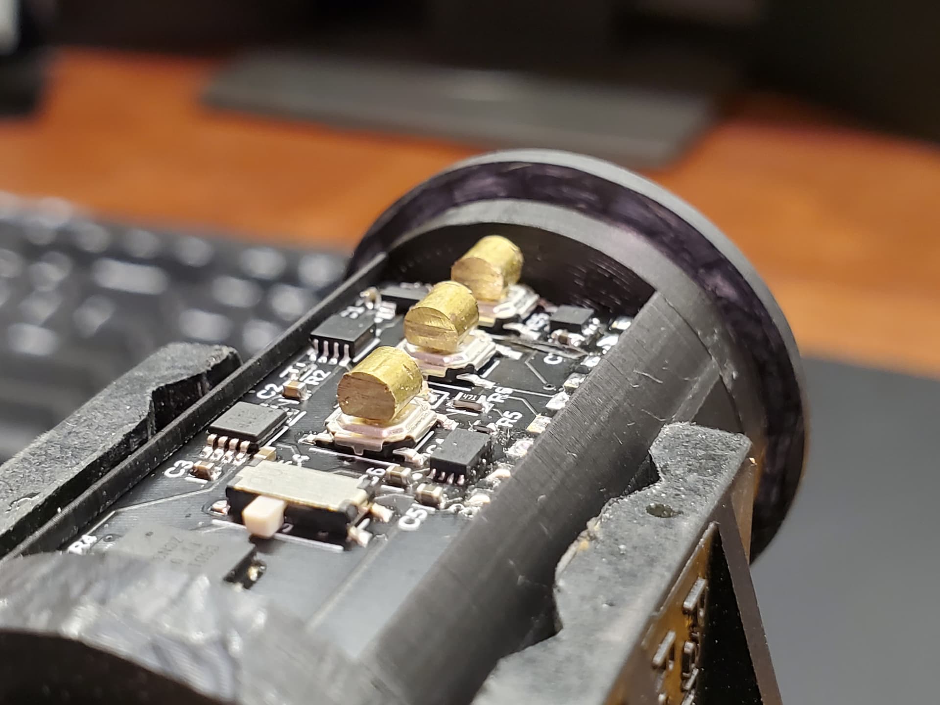
Following is a quick overview of the assembly process, starting with the “framework” assembly. I had some scraps of leftover black acrylic that happened to be the right height:
If anyone is interested in testing one of these out I have about 3 boards worth of spare parts I’d be willing to solder up and send out. If you want to make one yourself, let me know…if there is enough interest I will post the Gerber files and schematic.
Thanks! The dimensions are 0.5” x 1.225” x .063” (12.7mm x 31.12mm x 1.6mm). For reference, the V2 board in the picture above is the exact same size as a Proffieboard.
Seems pretty ideal for a blaster build. I have an F11-D in a box ready to build…was considering doing haptic feedback for it. Plus a kill switch is cool as a momentary. No losing the key!
I’m not sure what you mean, the vibration intensity correlates directly to how loud the sound is at any given time. If you mean false triggers, no, I’ve never had false clash triggers with haptics. Swings are a different story. In general, lowering the swing sensitivity a bit, and increasing the threshold for accent swings will get rid of any false triggers.
As far as mounting goes, the previous iterations (V1 & V2) install just like a soundboard:
However, V3 has mounting slots on either side so that it can be installed with two 1-64 button head cap screws. Having a sturdy mounting is important to effectively transfer the vibrations to the rest of the hilt.
I’d be interested to see a “2.5” that reimplements the charging but retains some of the improvements of the 3 considering (afaik) the proffiev3 is still delayed due to shortages?
I did think about keeping it on there. However, in the end it makes a lot of sense to keep the charging circuit outside the hilt.
After all, you only use it while you’re charging the saber, so why take up space with an item that is only used while you are not using the saber?
I’ve been working on an in-line charging circuit that can be spliced into a USB cable ( C or B ). Same effect and convenience, without the space wasted in the hilt. I have tried it with a V2 board in-line, and it does work.
I recently learned something interesting about FETs: they are bidirectional. What that means is that is possible to charge through the pogo pins, if the board is powering the blade. We can use blade Id to set up an always-on preset, and a blade plug with a charge port and a blade Id resistor and poof; you have charging with no extra components in the hilt.
Very interesting…I’ve seen FETs used bidirectionally in battery protection circuits, but never thought how it might be used to backflush charging current through the blade FETs.
So, bad news…Saber shield V3 does not work…neither function. Well, not exactly. Both functions work, just not in the way I was wanting. Which basically means they don’t work now that I think about it.
The kill switch works maybe every 20 button presses. I must have calculated the RC time constant wrong, because the switch bounce is wreaking havoc on the flip flop output. So, it is very unstable.
The motor circuit works like a charm, however the inertia of the rotor prevents any sort of meaningful resolution of the sound variation to come through. Apparently moving away from a dedicated driver chip with braking was a mistake.
So I am going to start work on V4. Instead of trying to cram a bunch of features on the board, it is going to be a kill switch only. Since we have discovered charging though the emitter, the charging function is irrelevant, and you can buy breakout boards for the haptic chips.
V4 preliminary design is complete. Last checkthrough before ordering the PCB.
Changes from V3:
This version has the kill switch functionality only.
Larger pads for wire connections
Status output for constant-on LED when board is powered. It has a 0603 pad for a resistor, so you can wire the output to a AV switch and not have to bother with an axial resistor.
Smaller footprint: the length is reduced from 1.225" down to 1.025"