Hi everyone. I have designed a PCB which takes some of the headache out of wiring a lightsaber hilt, by providing power/aux switches, momentary-based kill switch, battery charging, and haptic feedback. I’m interested to hear what everyone thinks.
Every aspect of the board is documented in this Google Doc: Saber Shield
I built a V1 prototype of the board, but it lacked ESD protection and a few features. The layout was also pretty bad. However, it did work, and I am integrating it into my Council Saber build.
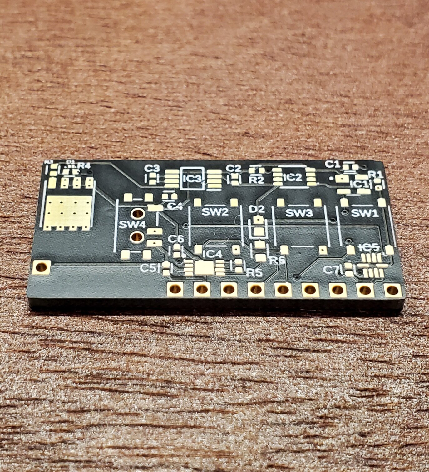
This is the bare PCB of the V1 board:
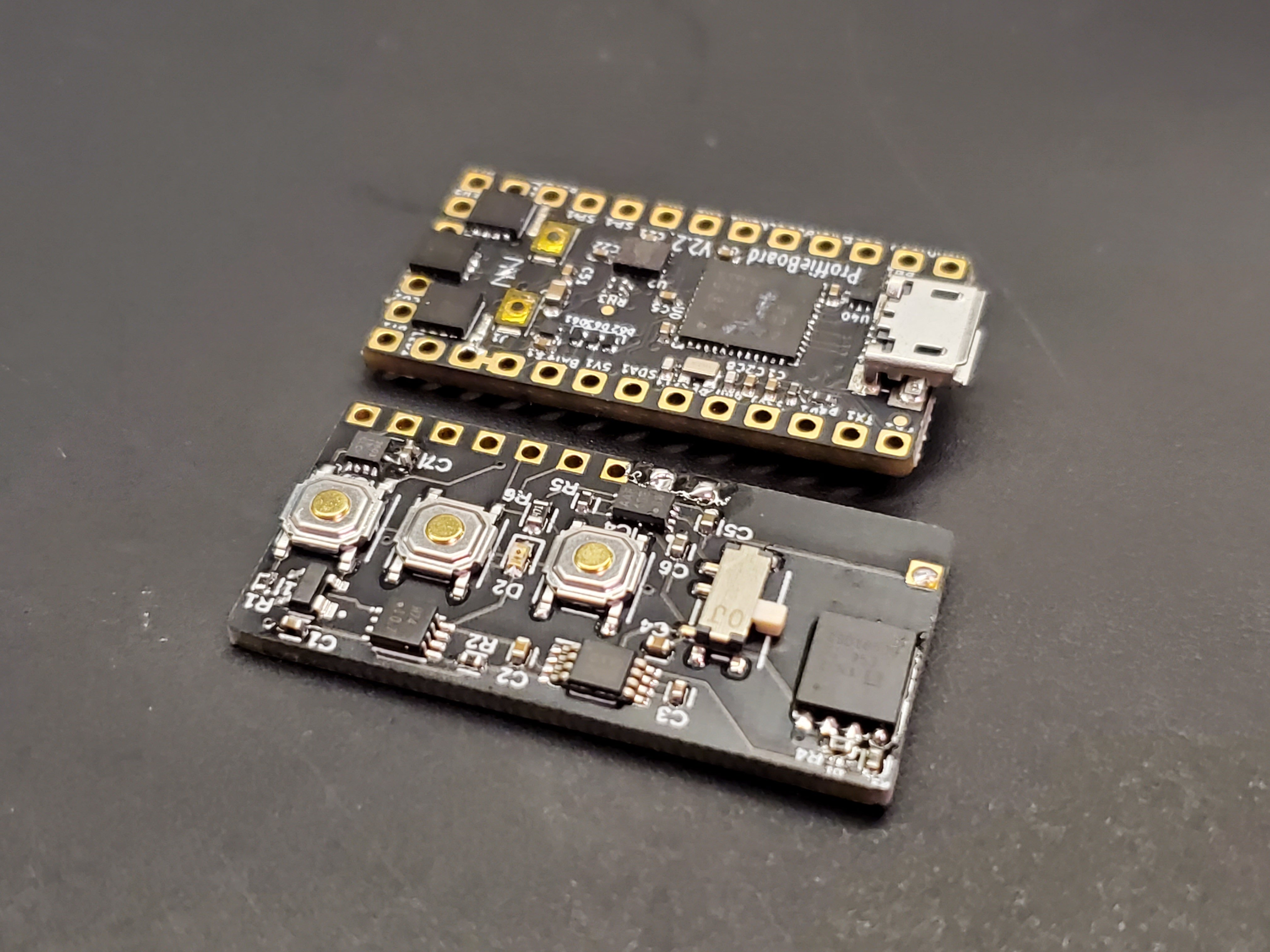
Here it is with all components soldered, next to a Proffieboard 2.2:
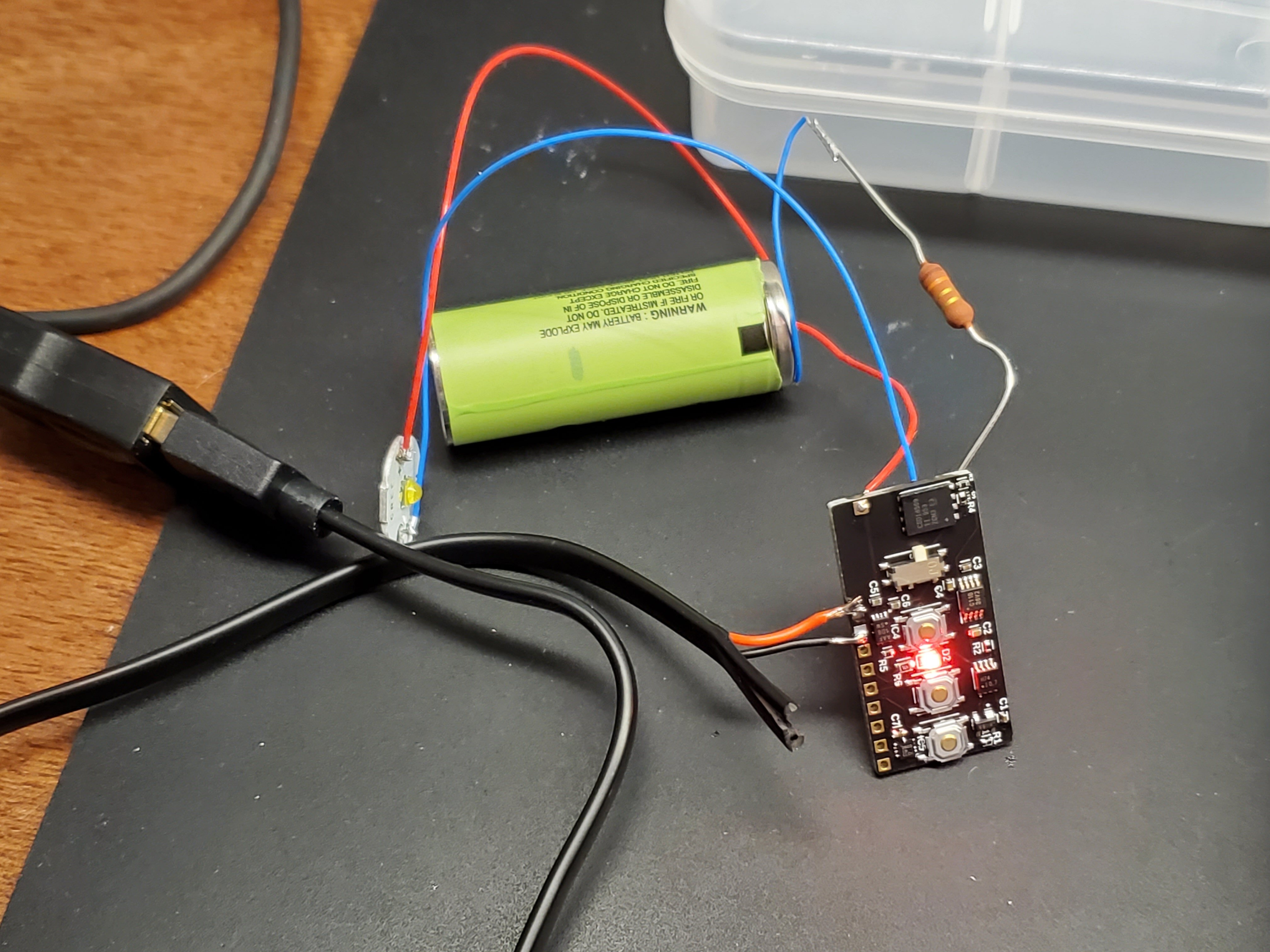
Testing the charging function (notice the red indicator led):
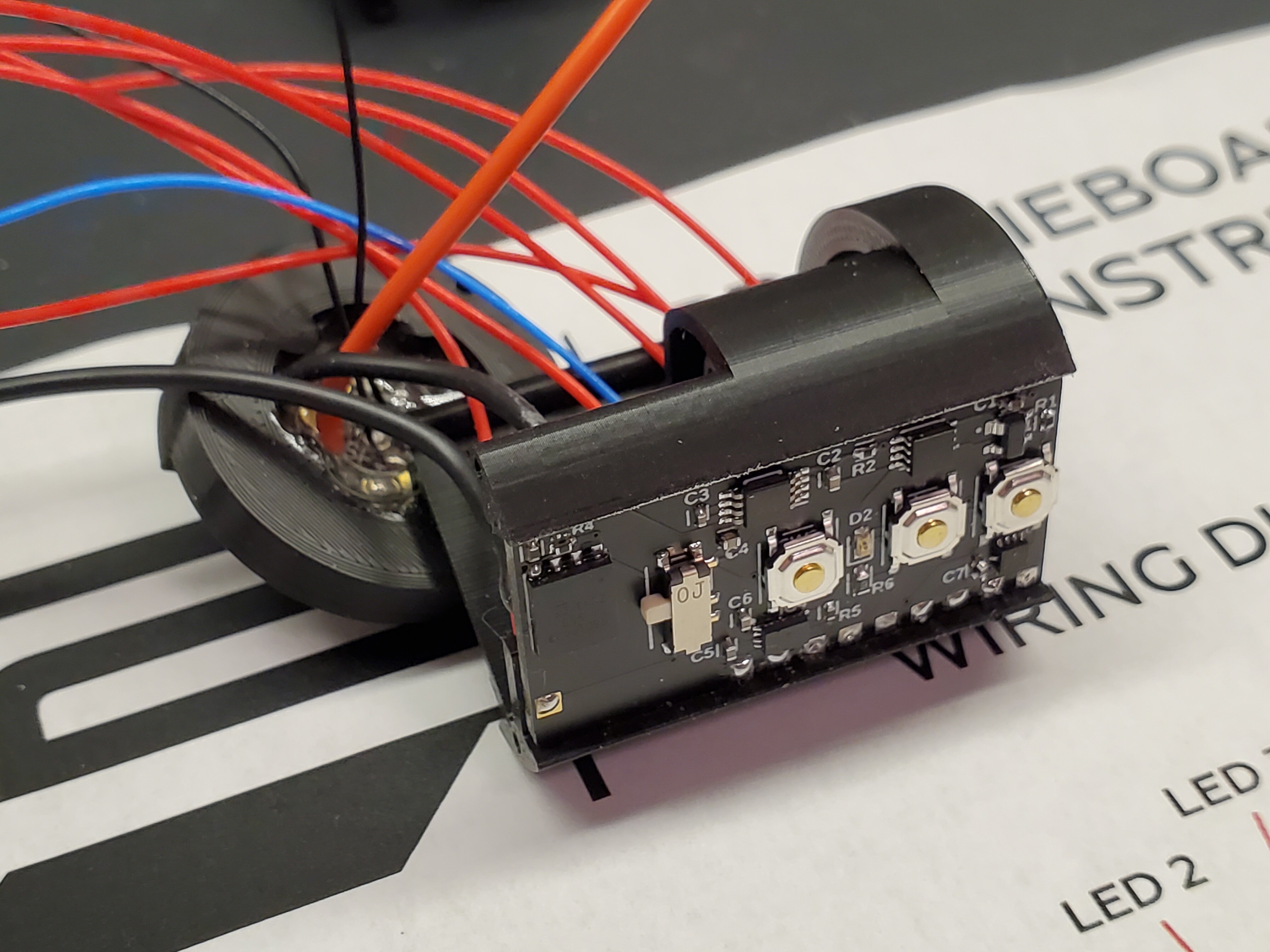
Finally, here is a shot of it being installed into the brain module of my council saber build:
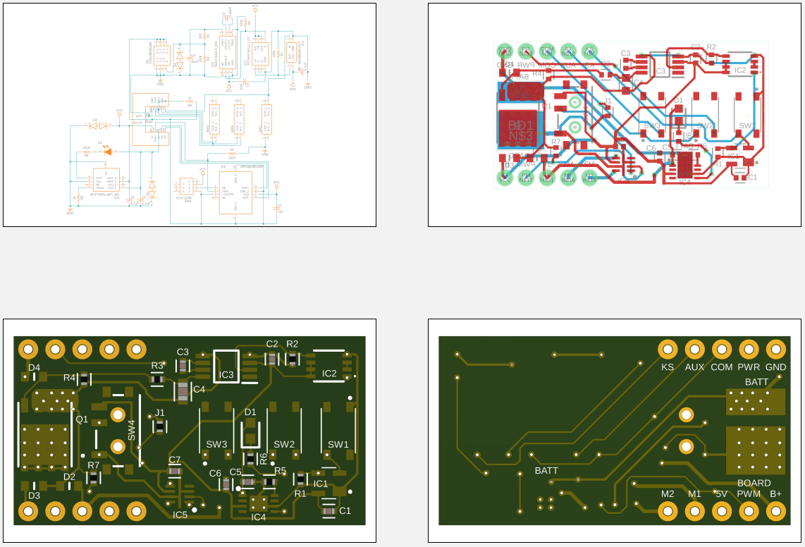
V2 of the board is much improved. It includes ESD protection, lower idle current, improved board layout, and smaller/taller switches. It is also 1.3" long, instead of 1.4". Please excuse my horrendous usage of schematics and poor board layout…this is only my third PCB design.
I should receive the new batch of PCB’s within a week or so, and will post an update with how it looks all soldered-up.
4 Likes
That is pretty cool.
However, I have questions:
- what is the 5v regulator for? (I can’t seem to read the circuit diagram)
- I’m guessing the sliding switch is an on/off switch? How will people access it?
- Fixed button locations will limit what hilts it works with. Did you have a particular hilt (or set of hilts) in mind?
- Is this open source? (If so, make sure you pick a proper license!)
This is very intriguing!
So if I’ve read your document right sw3 is actually a kill switch for the proffie board? ( giving a momentary push button externally accessible on the hilt? )
I like the idea of the haptic feedback feature and the option of using the slide switch to disable this function.
And your build look very good too👍
Let us know how it works out for you.
profezzorn:
-
The 5V regulator is simply there to drive the gate of the power mosfet at a constant voltage to get a good Rds value (1.5-2 mOhm). Although a fully charged battery would work okay at first, once you reached 3.5 volts or so Rds would start to increase exponentially…probably leading to thermal runaway.
-
The sliding switch is only there to enable/disable the haptic chip. It’s really just a convenience. You could also just enable/disable the PWM output of the Proffie, but it is not as simple with Plecter boards.
-
True, the buttons locations are not variable. The aux button is further from the other two in order to allow for a larger button size. At the end of the day, the switches being on the board is really just an option for anyone who wants to use them in a switch box…the board works just fine without either switch connected. As far as the kill switch goes, there are breakout pads for it, so it is very easy to wire up an external switch.
-
I don’t intend on making these to sell…I just put a lot of work into it, and figured others might be interested in making their own. So yes, open-source it is. I need to research licenses I guess.
Driftrotor:
Thank you for the kind words! Yes, SW3 is a kill switch for the sound board. It electrically disconnects the board ground from the battery negative. The only current consumption after that is the chips which make up the kill switch system (about 50uA).
2 Likes
I’m fairly certain that you can find mosfets with a gate threshold of 1 volt, or even less. With a FET like that, having a 5v regulator would not be required.
Have you been working with haptics for your sabers? I don’t know a lot of people who do, and some of them have been having problems with false clashes.
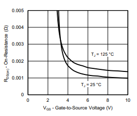
You’re right i’m sure, but I did quite a bit of digging to find a power fet with a low gate threshold. For all the ones I looked at, even if the gate threshold is 1V…like this one: https://www.mouser.com/datasheet/2/427/sira62dp-1766481.pdf …it still shows the Rds only dropping to acceptable levels around 4-6 volts for Vgs.
As far as the haptics go, up to this point I have used Plecter boards coupled to a Pololu DRV8838 breakout board. Generally adjusting the swing sensitivity helps filter out any false triggers, but I have no experience implementing it with Proffieboard (yet). I’m also using an Xbox 1 controller trigger vibration motor for my current build, so there will definitely be some pretty heavy movement. I imagine the mass of the hilt and how tightly the soundboard is coupled to the chassis will have some effect.
1 Like
For the Rds, I suppose it depends on what you mean by “acceptable levels”, but it is disconcerning when they don’t show what the RdS would be below 3 volts…
How about this one?
https://www.mouser.com/datasheet/2/115/DMN1004UFV-1112830.pdf
Oh, and on the haptics, please let us know how that works out for you!
I only see thing traces coming from the FET. That might not be enough to carry the current needed. Or is there some fill zones that I can’t see in the drawing?
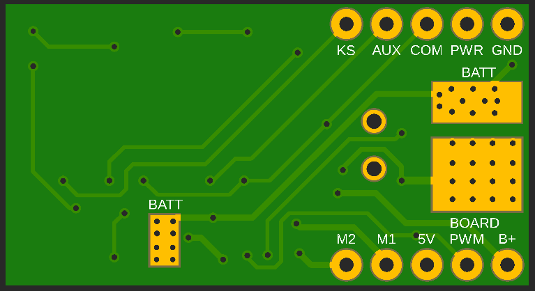
For some reason the solder mask does not show up in the Fusion preview. Here’s what the bottom of the board looks like:
There are a bunch of thermal vias between the mosfet mounting pad and the bottom copper…since the mosfet has such a low Rds, the power dissipation only needs to be about 0.22 watts at 10A.
I’m not worried about heat dissipation, I’m worried about the current-carrying capabilities of the board itself. Depending on the thickness of the copper layers you usually need a trace that is a couple of millimeters wide to carry 10 amps. I don’t really see that on your board.
You solder your battery and board wires directly to the exposed pads on the underside of the board…the Moffett mounts to the top, and the vias you see in the picture connect the top and bottom copper. There are no traces carrying the main load current.
2 Likes
Ah, that explains it.
That also improves the heat dissipation quite a bit, as the wires can pull heat away.
1 Like