I saw a video on KR Kestis Goth Master chassis built by Sabersforever using bladeID with Shtok rotary pcbs to switch between regular fonts and crossguard fonts depending on which upper hilt part is used. I want to make sure if my understanding is correct on how it was done by asking about it here and also some questions about using chassis pcbs in other ways.
Questions:
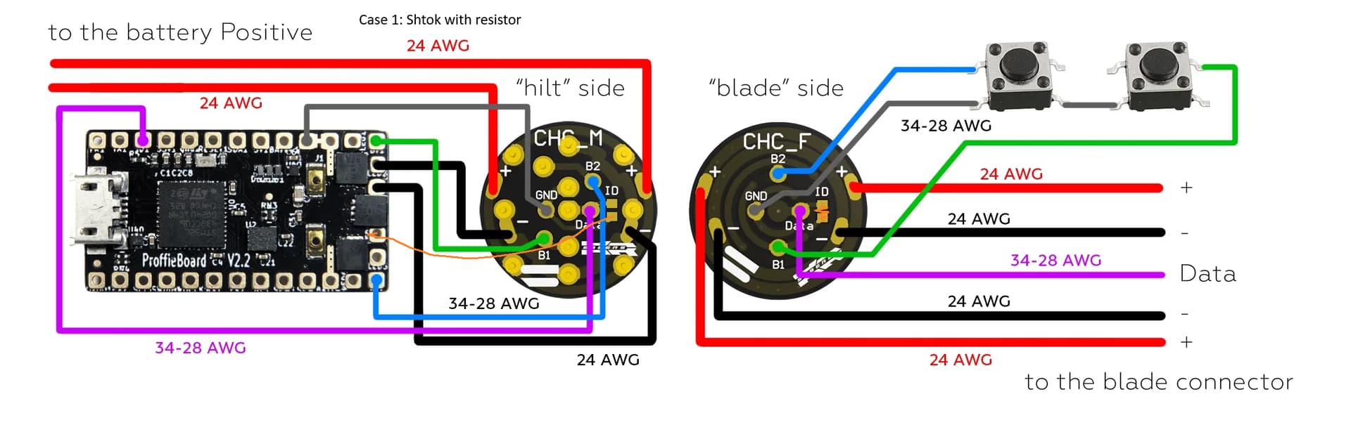
Firstly, regarding the Kestis master chassis, is it correct you would put a resistor connecting the two ID pads in the upper section and in the swappable section, you can scan for that resistor value using wire from a proffie led pad to the connector id pad?
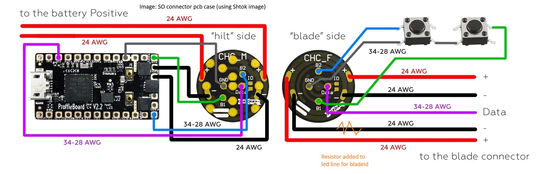
If I used an S.O. pcb with a second data pad, where would the resistor be connected to to get bladeid to work? Would it be between the led wire to the pixel connector? I could also wire a data wire to use as blade detect but would there be any use for it?
(I’m reusing Shtok’s image for convenience)
So, i don’t know this specific PCBs, but I will try to answer anyways.
So, if it’s an ID resistor, I’m going to assume that we’re talking about “Blade ID”. Blade ID works through the data pad, not any of the LED* pads. Is the hilt side PCB illuminated? If so, those leds must be on a separate data pad for blade ID to work properly.
This sounds super weird to me, and I don’t know why there are ID pads on the hilt side.
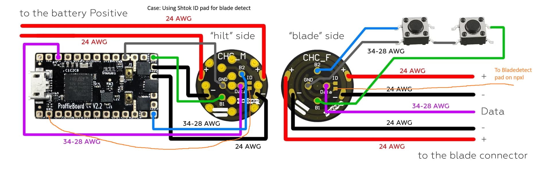
Blade Detect is different from Blade ID and does not use a resistor, instead if uses a separate pad which shorts to BATT- when the blade (or whatever) is connected.
It has to be between LED- (to the blade) and data (to the blade). I assume that’s what the ID pads do.