I’m currently mapping out my first install, and I just wanted to make sure I understand how wiring the Killswitch works, and I also have a second question about Neopixel Connectors.
So from the wiring diagrams, it appears that the Killswitch goes to the Battery Positive, and the soundboard positive… However, I read online that you’re not supposed to do this because it will send too much power through the Killswitch. I’m watching a Saberbay install tutorial right now, and he appears to be wiring to the battery negative, and the Soundboard negative instead of the positives. Am I just imagining things?
My other question is regarding the Neopixel Connectors. I’ve read online that you can wire your positives and negatives to the Neopixel Connectors to cut down on splicing wires together. Some people say this is a cleaner way to install.
If anyone can clarify these things for me, it would be greatly appreciated.
Yes it will cut down on splicing and yes it can be cleaner but that also means that all your electricity will have to go through your Proffieboard and killswitch. So a very “hungry” blade will draw a lot of electricity through both.
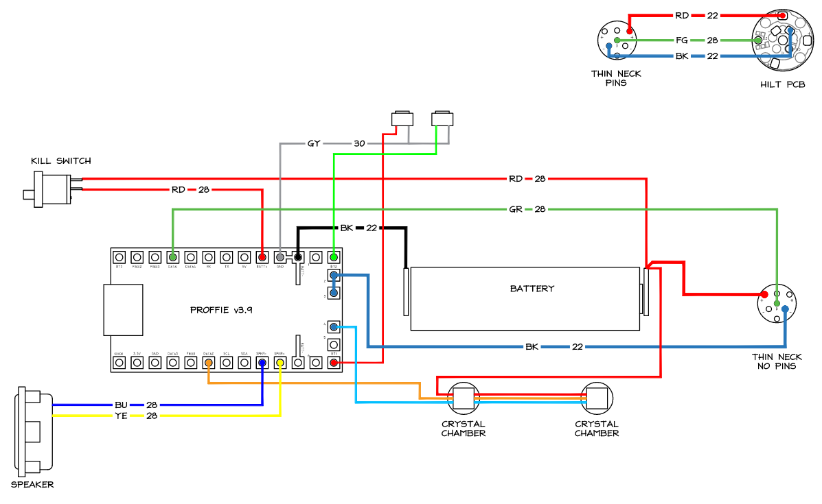
If you compare the wiring diagram for Proffieboard v2 & v3:
I personally think that the v2 does it better because only the power for the Proffieboard goes through the Proffieboard & killswitch. The Neopixel is fed directly from the battery without going through the Proffieboard & killswitch.
As far as using the killswitch on the pos or neg:
if you wire as per the v3 diagram: everything will go through the killswitch and the board, so it makes no difference
but if you wire as per the v2 diagram:
if your killswitch is on the pos then only the power for the board will go through your killswicth
if your killswitch is on the neg then the whole power will go through it.
Both diagrams will achieve the same results as long as your killswitch is highamp tolerant. With the new blades with very high led count (very power hungry) I would use the v2 diagram for my v3 board with the killswitch on the pos.
Edit: if you look at the Proffie manual from Shtok that I posted in your previous thread, the kill switch is always on the pos between the battery and the Proffieboard & never interrupts the positive wire to the NPXL connector.
Okay so let me get this straight. What you’re saying is that I should splice the wire onto the positive battery tab, and send one positive directly to the Neo Pixel Connector, and one positive cable to the battery positive passing through the Killswitch? Is that right?
I think my main question is, why would someone wire directly to the negatives instead of the positives? How does that work?
Also my reasoning for asking about the Shtok connector wiring having multiple outlets for positive and negatives, is because in the future i want to do a very feature heavy build on a Creepy Uncle V2, and there’s only one spot for battery positive on the Proffie Board.
Thank you for getting back to me. Im trying my best to absorb as much information as I can. I’m new to wiring electronics. I’m probably way overthinking it.
The negative wire between bat neg and Proffieboard will always get 100% of the current used (Amps) so if you place your killswitch there, 100% of the power will go through it too. I would not do that!
from the v3 generator, you will see that the pos wires are all spliced together in one place (but ideally they should be spliced before the kill switch). None of the led pos wires need to be on the Proffieboard, only the data & neg wires need to be on the board.
Just to be clear about your first response to my question about wiring all of the positives to the Neo Pixel Connector… I wouldn’t be able to do this if I were using your recommended (V2) wiring diagram setup correct?
Thanks man, I appreciate your patience. If I run into any issues along the way I may need to come back and brush up on some knowledge. Everything we’ve discussed has been very helpful.
I find this discussion hard to follow, and I’m not certain that everybody is on the same page. I apologize if this answer is long and redundant, but here goes…
First up, there are pros and cons of having all your power go through a kill switch or kill key:
If all your power goes through a turn-off device, then you can be sure that everything turns off 100%, and the battery does not drain when the saber is turned off. (Other than self-drain, which causes a batter to drain even if not plugged in.)
On other hand, having all the power go through the kill switch means that the kill switch has to withstand 10+ amps, which limits which switches you can use. Note that the “high amp” switch we all use is rated for 3A. It’s probably fine to use it the way we do, but it’s longer and complicated discussion that I won’t go into here.
There have been a few reported cases where kill switches didn’t work properly when you didn’t kill the power to the blade. It’s not clear exactly what happened in those cases, but somehow power found a way through the blade (or through accent LEDs) to power the board even when the kill switch was off. Most people do not seem to have this problem, but it cannot happen if you cut all the power.
I assume you mean after you click the “kill switch” button…
As mentioned above, there are pros and cons.
Cutting the power works just as well on the negative side as it does on the positive side.
Here is an example that does just that:
However, the low-power option (only cutting the power that goes to the board, not the power that goes to the blade) is really only available on the positive side, since the power to the blade goes though the board on the negative side. (but not on the positive side.)
UNLESS…
It is possible to connect the - on the pogo pin board directly to - on the battery, similar to how it works on the + side. If you do this, then the board is not able to cut the power to the blade anymore, which significantly reduces the standby time, but only if the blade is in. When the blade is removed from the hilt, the standby time would be the same.
(I’m not sure if this was what you guys were talking about above or not though. The descriptions are a little vague in some cases.)
If you bypass the board in this way on the negative side, you need to splice in a connection to GND on the board, same as for the plus side, and if you put a kill switch on that wire, it won’t get the full blade power, same as on the plus side. Obviously, this is not how we normally do it, and I wouldn’t recommend it, but it is possible.
So how would you personally recommend wiring the Killswitch with the pros and cons in mind? What we’re discussing, is how to properly wire the Killswitch. I just hear so many mixed reactions about how to properly wire it, and I can’t seem to get a clear answer.
The unclear answer is the correct answer so far. The skill of installation includes a lot of decision making, based on the hilt in front of you.
I have sabers with kill switches on the positive, and sabers with barrel jacks and kill keys on the negative.
If there are small accents high in the chassis (like for a crystal chamber), I recommend running wires off of the hilt pogo pcb to power them.
You might also have brass tubes or little windows that need straight lines running up and down…it all adds up to the what you need. You could even have a super simple chassis, or no chassis at all and just have a nice wire nest.
Try a wiring diagram and post it and someone will tell you if you’re going to ruin your project, but a lot of wiring is style (choice) or dictated by the chassis (demand).
I understand what you’re saying. I will be sure to post my wiring diagrams during my first few builds, and have you guys look them over just in case. I appreciate the help.
Speaking of brass tubes, is there a reason they have to be brass? And I’m guessing I’ll need a dremel to cut them down to size right?
No, they can be any material. Brass is popular because it’s strong and looks good. It can be used for structural support and as a wire channel. This would be for smaller, decorative work. You can use a dremmel, but I suggest a tube cutter like:
You’ll have to deburr the interior edges (remove the sharp or jagged stuff that get pushed slightly inward). Bigger tubes means a bigger cutter of course. And rods can often be just cut with tin snips and sanded.
As an example, I did this chassis and it required both rods and tubes.
The crystal chamber was at the top, so I wired the pixels to the pogo pcb at the top of the chassis for power and oterhwise did what @orntar is showing in his diagram. Kill switch on the positive.
My current proffie project has a build log, which I just updated:
This will have barrel jacks with the kill key creating a switched negative.
Thank you for the link. Btw when you say Pogo PCB, you’re talking about the “Neo Pixel Connector/Hiltside Connector” right? Just want to make sure I’m on the same page.
I learned the hard way, after I started collecting sabers last year, that “deep sleep mode” leaves you with a dead battery pretty quickly. I’m now designing my own series of sabers, and I’m trying to decide whether to use the most common system (where the switch merely interrupts the positive connection between the battery and the soundboard) or the seemingly less common “all kill” switch (where it also interrupts the positive connection between the battery and the neopixel blade). I would be keen on an all-kill switch if it would make a difference to battery drain.
So I guess my question is, does an attached blade or blade plug drain battery power even when power to the board is killed?
Or to put it another way, does a board-kill switch already eliminate battery drain, such that an all-kill switch would offer no greater performance in that respect?
Proffieboard currently does not have a deep sleep.
But the standby is usually fairly good and lasts ~6 months or so. However, that sort of standby is not always possible, and if the blade is left powered all the time, standby time is only a day or two. This happens when you either run a style that never turns off, or if you run a style that is black, but ProffieOS is unable to detect that the blade can be turned off. If you find that this is happening, but nothing is actually on, please report it here and I’ll see if I can fix it.
No. (but see caveat below)
There are pulldown resistors on the board that should shut the FETs off.
If the pulldowns are not working, or the manfacturer chose the FETs poorly, power could still leak.
For some configurations, power can still drain though the data line. Having a resistor on the data line will minimize and/or eliminate this problem, but you should be aware that it is possible. I have only seen this happen when people wire up accents without resistors though.
As usual, the best way to find out if a design has a problem is to measure.
Get a multimeter that can do microamps, hook it up and see what happens.
Thanks! My saber collection is almost entirely Sabertrios with CFX boards. The batteries don’t last many days (sometimes very few days, it seems) unless I use the kill switches. It sounds like your boards have better power conservation to begin with. Happily, once I complete my basic design choices and concept art, I’ll be turning my projects over to professional sabersmiths to do the manufacturing, installation, and programming.