Proffie v3 with a neopixel blade that won't light up

If data2 is not hooked up it is not going to work. Are you sure you are uploading what you think is uploading ? You can try to remove the first “S” from the first “Styleptr” in your config. If you verify and there is no error, you are not modifying the correct file. If there is a compile error (as it should), then great, put the “S” back because you are changing the correct file.

Did your blade and pcb light up when you did the blade length finder procedure?

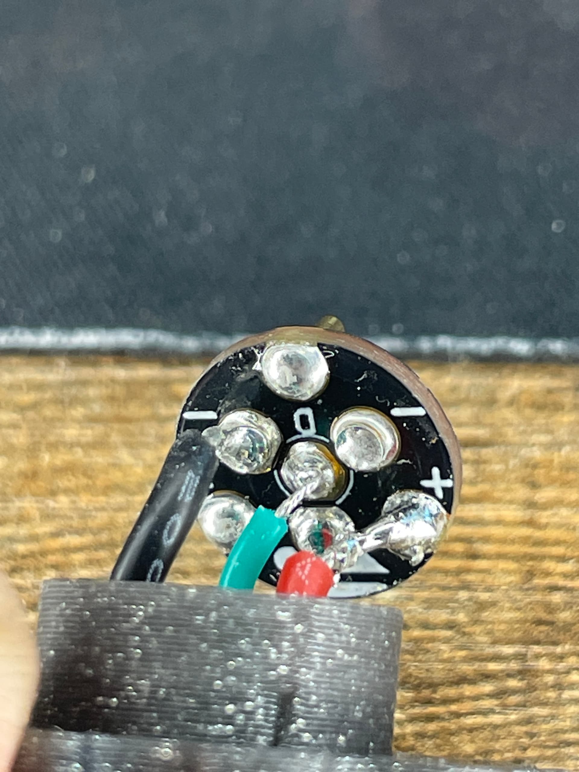
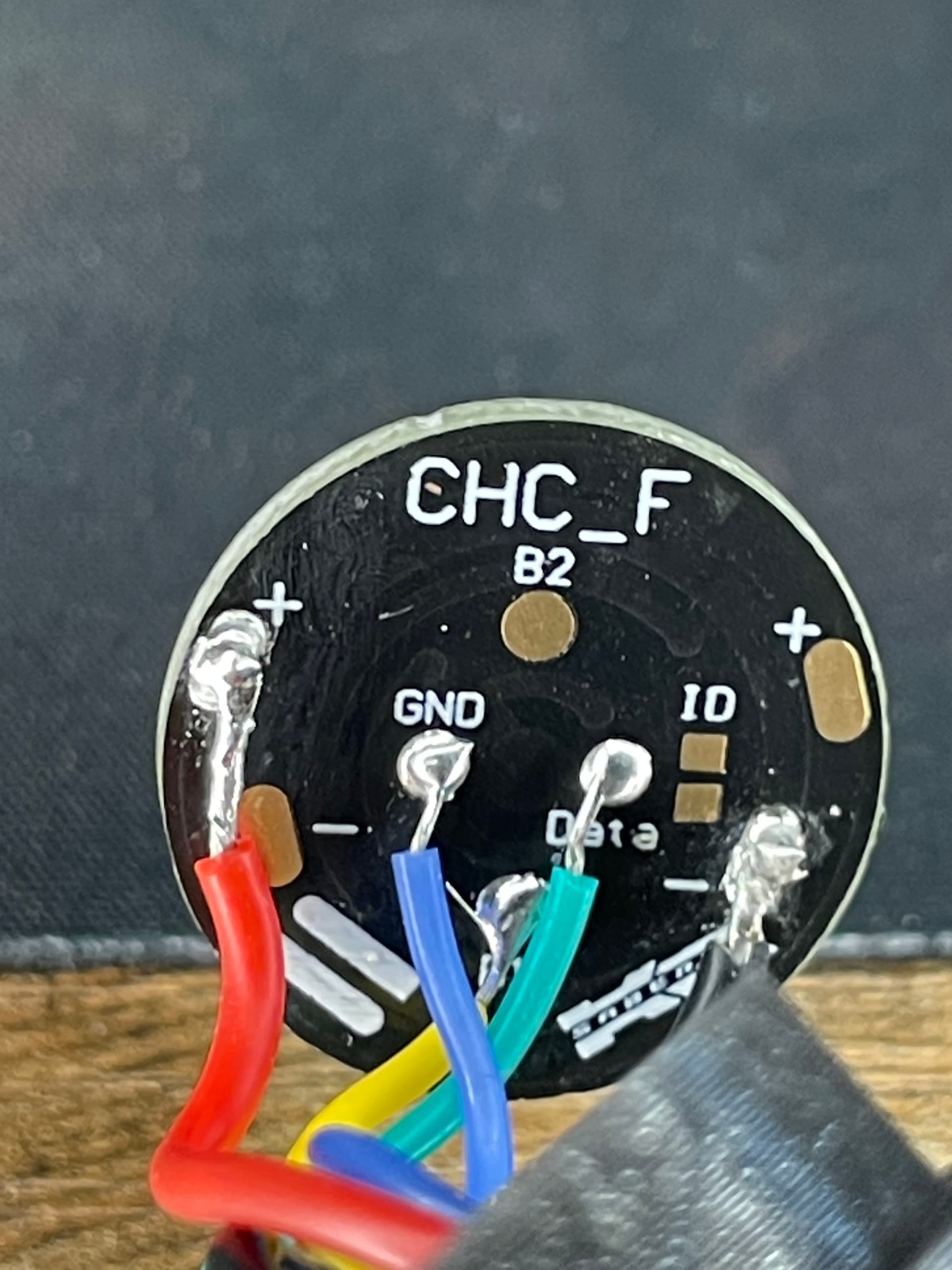
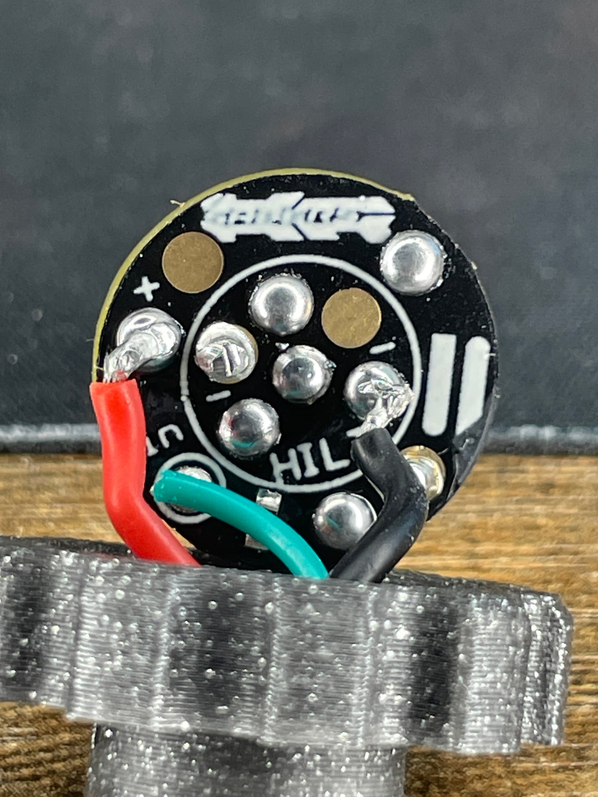
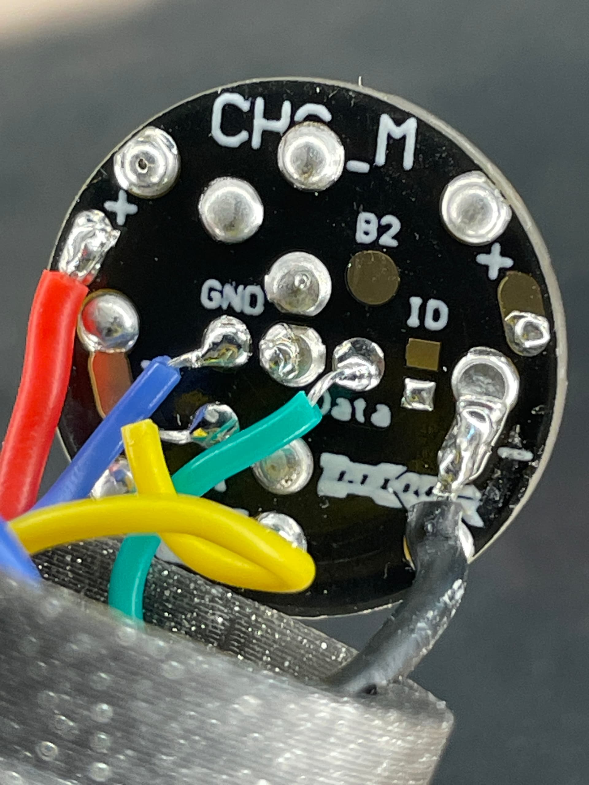
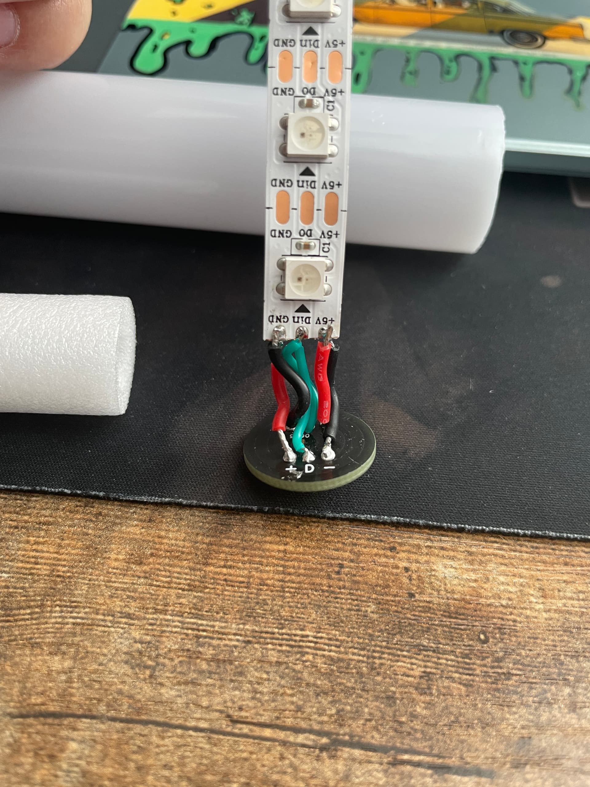
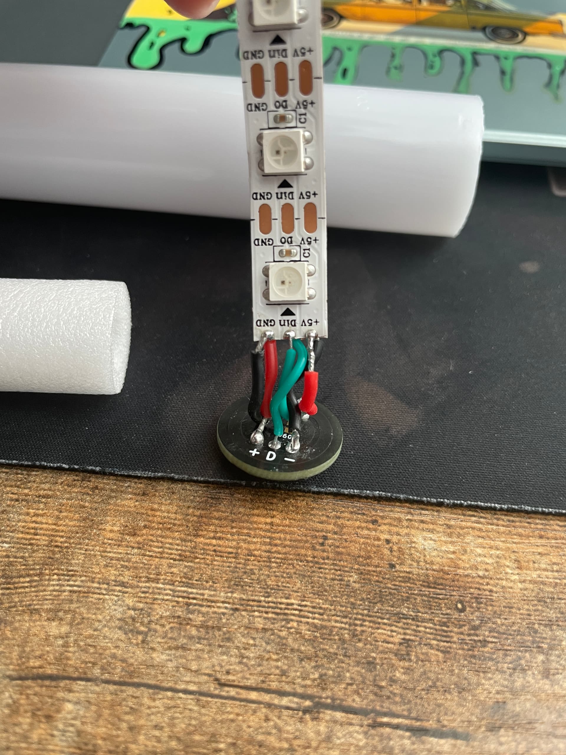
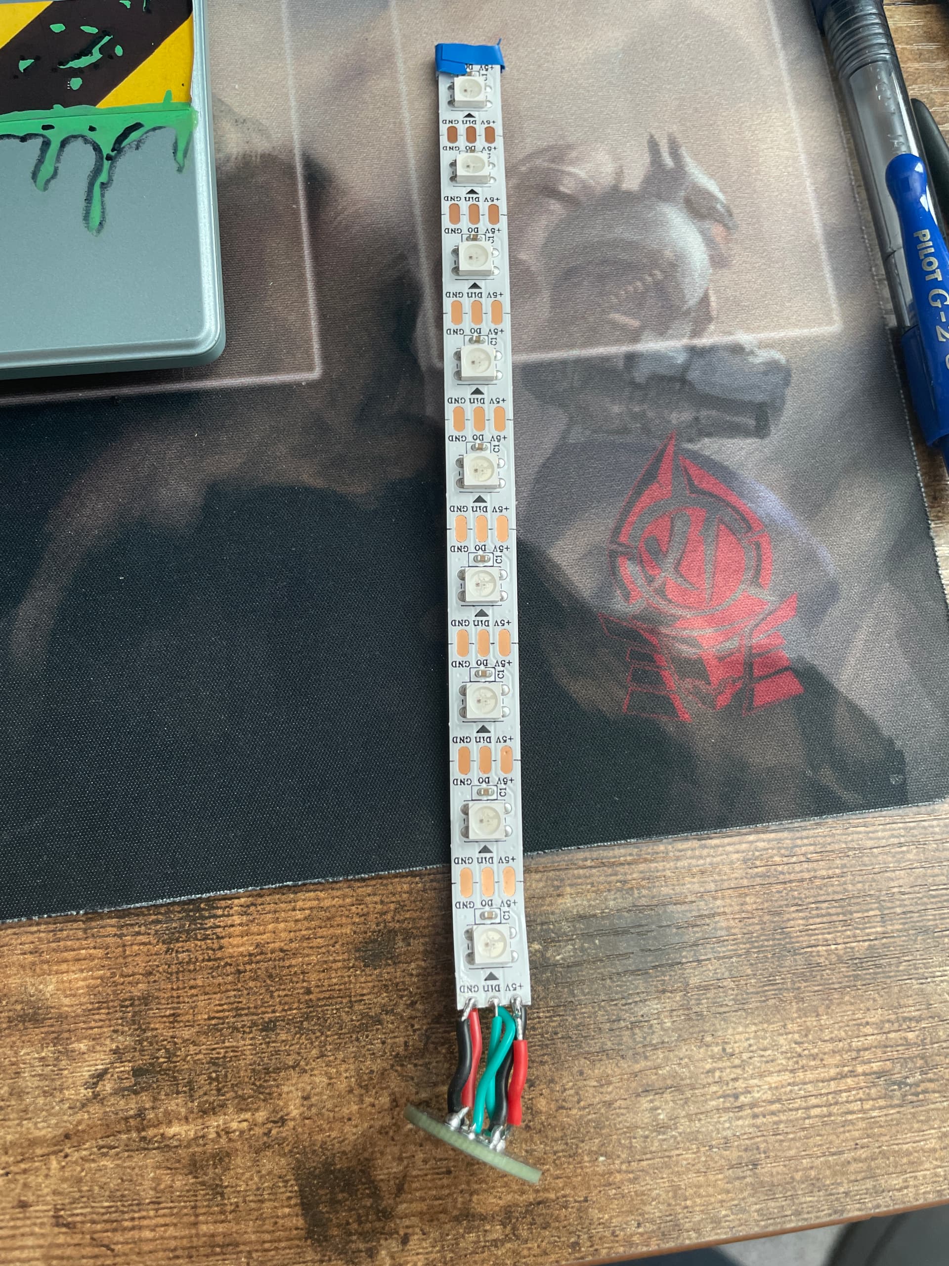
Clearly from the photo, it is all hooked up to data1 (bladePin) so you can forget trying blade2Pin.

In this one the numbers are wrong

But this one should now work using bladePin (data1) and the correct numbers:

{ 0, 
SubBlade(30, 141, WS281XBladePtr<142, bladePin, Color8::GRB, PowerPINS<bladePowerPin2, bladePowerPin3> >()), // this is your main blade with 112 leds
    SubBladeWithStride(0, 29, 2, nullptr), // this is your pcb part1 with 15 leds (1 out of every 2 starting at 0)
    SubBladeWithStride(1, 29, 2, nullptr), // this is your pcb part2 with 15 leds (1 out of every 2 starting at 1)
   CONFIGARRAY(presets) },
};

i am trying the blade counting procdure just having a bit of trouble getting it to verify so i can test it. I am very sure i am uploading the ones i edit, i open the .h file i have in the config folder for proffie os and edit that then hit save in notebook before i verify it on arduino. How do i write the preset for the blade counting procedure i keep getting this error with it.

In file included from C:\Users\franc\Downloads\ProffieOS\ProffieOS.ino:621:
C:\Users\franc\Downloads\ProffieOS\config\Cestis_Saber_1.h:76:2: error: expected '}' before '{' token
   76 |  { "TeensySF", "tracks/venus.wav",
      |  ^
C:\Users\franc\Downloads\ProffieOS\config\Cestis_Saber_1.h:19:20: note: to match this '{'
   19 | Preset presets[] = {
      |                    ^
C:\Users\franc\Downloads\ProffieOS\config\Cestis_Saber_1.h:76:2: error: expected ',' or ';' before '{' token
   76 |  { "TeensySF", "tracks/venus.wav",
      |  ^
C:\Users\franc\Downloads\ProffieOS\config\Cestis_Saber_1.h:79:34: error: expected unqualified-id before ',' token
   79 |     StylePtr<LengthFinder<>>(), },
      |                                  ^
C:\Users\franc\Downloads\ProffieOS\config\Cestis_Saber_1.h:80:1: error: expected unqualified-id before '}' token
   80 | };
      | ^
C:\Users\franc\Downloads\ProffieOS\config\Cestis_Saber_1.h:80:1: error: expected declaration before '}' token
exit status 1

Compilation error: expected '}' before '{' token

Nevermind i figured it out, i just tried it with my test blade in, i cycle to it and it just counts one three times then thats it. No twist counting or anything, i am not sure what the problem may be for it.

I’m not sure about the pixel order on the ECO V4. That could be a problem when creating the subblade. I’d remove the stride component.

So based on:

It would look like:

BladeConfig blades[] = {
  { 0,
    SubBlade(30, 141, WS281XBladePtr<142, bladePin, Color8::GRB, PowerPINS<bladePowerPin2, bladePowerPin3>>()),	
    SubBlade(0, 29, NULL),
    CONFIGARRAY(presets),
  }
};

Which I created using the info found here:

That gives you main blade as blade1 and the pcb LEDs as blade2. We can look at getting nice ring animations using stride after everything is running (which is why you’d want stride).

Then there’s your photo, which shows lots of extra flux all over the board. You might have a short somewhere, which will trip the battery protection circuit. The soldering looks pretty good, but you want to go for an even dome of solder that covers the pads completely. Reflowing may help. I’d for sure clean the flux off with a toothbrush and something like WD-40 Contact Cleaner.

I saw a few typos in tries at the config. Rather than trying to sort through it, here’s a sample config with my try with my suggested blade array, for a V3 with 1 button and 2 blades (one of which is the pcb)


#ifdef CONFIG_TOP
#include "proffieboard_v3_config.h"
#define NUM_BLADES 2
#define NUM_BUTTONS 1
#define VOLUME 1000
const unsigned int maxLedsPerStrip = 144;
#define CLASH_THRESHOLD_G 1.0
#define ENABLE_AUDIO
#define ENABLE_MOTION
#define ENABLE_WS2811
#define ENABLE_SD
#endif

#ifdef CONFIG_PRESETS
Preset presets[] = {
   { "TeensySF", "tracks/venus.wav", 
    StyleNormalPtr<CYAN, WHITE, 300, 800>(), 
    StyleNormalPtr<CYAN, WHITE, 300, 800>(), "cyan"},
 };
  BladeConfig blades[] = {
  { 0,
    SubBlade(30, 141, WS281XBladePtr<142, bladePin, Color8::GRB, PowerPINS<bladePowerPin2, bladePowerPin3>>()), 
    SubBlade(0, 29, NULL),
    CONFIGARRAY(presets),
  }
};

#endif

#ifdef CONFIG_BUTTONS
Button PowerButton(BUTTON_POWER, powerButtonPin, "pow");
#endif

Okay awesome thank you! I will definitely try that and I completely forgot about cleaning the board! I will definitely do that, do you think 90% isopropyl alcohol would work too?

Yup. Just let it dry for a few sec

Or minutes. If I want sec, I use a hairdryer on cold.

1 Like

so i cleaned the board and added the new config that you provided and unfortunately, the same result… i cannot think of what i am doing wrong, maybe my saber is defective but still no lights in the blade sadly.

I asked this earlier, but could I possibly have the wrong type of neopixel strip for my blade? Since I can get everything else working, could that be possible?

Using a different kind of of neopixel generally cause the colors to come out wrong, but it still lights up.

If the pogo pin PCB lights up, but not the blade, then there are two possible reasons:

  1. the data that the board outputs, ends at 16 pixels (or however many pixels the pogo pin board has.)
  2. it’s a wiring problem somewhere

Problem (1) should be easy to detect and fix, just make all blades long in your config file. If the blade still doesn’t light up, then it’s not (1).

Problem (2) is a little harder, because you have to find where the signal (or power) doesn’t connect properly. A multimeter is the way to figure this out. Apart from using the beep mode (continuity), here are two pages that might help:

2 Likes

Okay cool i definitely try those, for making the blades long, would I just increase both the max LEDs and the sub blades in the configuration? Also I just went and got a multi meter, it’s going to be tricky but I will find a way to measure the data pins.

Yes, basically. I think this one we’ve done (and Profezzorn is confirming), but you can always try again.

I was frustrated with multimeters for while until I bought a new set of probes. The ones mine came with were unreliable or not sensitive enough.

Now I have:

With a set of these:

Ha, it’s showing the aligator clips but in the same section they are called “red-1” for their color and are just basic pin tip leads.

Reading over the instructions for testing again, it’s not too hard from a DIYer (as opposed to an engineer or installer) perspective. In fact this is what I’ll do from now on with my better gear.

If you catch a case of multimeter madness, you can try moving the data line to data2, 3, or 4 (desolder, solder in the new spot). The old pad can still have solder in it, just reflow it into a nice light bubble. When heating solder point already completed, tin your iron for faster heat transfer.

Then change it in you config (post config for help if needed).

But if you use that multimeter reading you can be sure before you do anything mechanical and possibly save time.

If you do have good data flow to data1, then check the connection to the back of the pcb, and finally to the tip of the center pin on the top.

i cannot thank you guys enough for all the help! Thank you so much, i will take note and being trying al the suggestions and letting you know as soon as i have the results and if it has been finally fixed. I also wanted to post pictures for the rest of my wiring of my saber. So you guys can get more reference for what’s going on. If there is anything that stands out please let me know, and thank you guys again!


First of all, the good part is that you got everything hooked up. That in iteslef is a challenge.

There are three things that I think could help.

First, the exposed wires are long enough that in a few spots I see the potential for them touching more than one pad, or an external conductive area.

This video was one of the first I watched to get an idea of wire flow and how to get as little wire exposed as possible. You want the wire jacket (coating) to be almost touching the pad. Like this:

That video came out before LEDs were on the tops of the pcb (the ring pcb was new tech), so it simplifies it.

Kal also did a nice video, and I used this to learn to start hooking up LED covered PCBs. HIs technique is a little different.

Second: You decided to wire directly to the presoldered pins, which is fine but can loosen the pins if your’re not careful. Those blank copper spots are meant to be pretinned and accept the wiring. The PCB ring is like a dart board, with data as the bullseye. The D1 pad has a trace that allows it to act like an extension cord, placed in the outer ring where the positives are, but traced inward to the bullseye. Otherwise, the outer ring is all positive and interally connected, and the inner ring is all negative. So you could move the (+) and (-) to the pads away from the pins for a clean start.

Baiscally the solder bubble should touch the very edge of the wire jacket, and your ends are too long to be safe, creating the potential for shorts. They might not happen when the pcbs are out of the chassis, but compressing them in is bending you wires right where they connect. Not so good.

Lastly, the solder points are a bit blobby (is that a word?) and look like they may be cold joints. That’s solved by a reflow, which will happen anyway if you cleanup the wire lengths.

Some additional helpful tools (that are relatively cheap) are magnififcation glasses, and a good set of tweezers. Mostly I use my fingers to do wire placement, but fine tipped tweezers can help you get a good angle at the contact point.

Good luck while you sort things! You’re close don’t give up :slight_smile:

Thank you again for all the help, so for a quick update. I did clean up my joints and I reflowed everything, cleaned up the wiring so not too much is exposed as well. Then, I tested everything with the multimeter, 1) I did the data pin check, check if there is data moving through the pin when the saber is ignited and the test proved there is data going through that center pin, was about 1 volt. 2) I did the voltage drop check; I checked both negative and positive paths for every component on the saber it has no drops. All parts had the voltage it needed to operate. After all this I plugged in the test blade to see if that hopefully changed anything, and was greeted with a dark blade still… So, I am going to move the data line as suggested and see if that hopefully works. I am going to move it data 2 and see if that works, I did have a question before I do. On the guide listed above that says to move the data line. It does mention a resistor that possibly needs to be added. It says that data 2 does not have a built-in resistor such as data 1. Am I going to need to add one in order to switch data pads or am I okay to just switch it over?

A lot of blades have the resistor on the pcb within. In that case no. Otherwise yes. Two resistors is no problem, so a data1 resistor and a blade side resistor are fine.

I’m starting to think it’s the blade. Curious case.

I do a resistor built into my hilt side pcb so that should be okay. I was sure that i built the blade right but i could be wrong. Here is the test blade i have been using and how i wired it.


I’m pretty sure I can see where the exposed wires by the pcb will cross and touch when compressed in place.

That’s gonna be a short and will likely cause problems and maybe permanent damage to the pixels.

Maybe try with new strips? Take a look at how Rob does it in the first video (from TCSS).

The good news is the board seems ok.

I’d give it all a trim and rewire :slight_smile:

To avoid “goose neck” wires, I recommend using silicone- or ptfe-coated wires when soldering. The insulation on such wires does not shrink or melt while soldering, which makes for much better results.

Mine are silicone coated and flexible, and I will try a new strip, I may also switch it to data 2 before I make the new blade strip