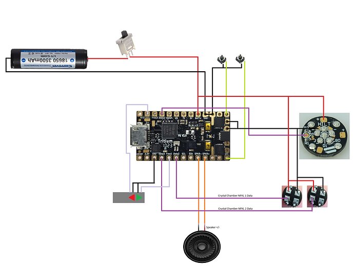
Hi again,
I’m doing an ROTJ Luke V1 build and wanted to make sure my wiring/blade configuration would be correct for the neopixel blade and control box accents. Could y’all please check my blade config and schematic?
BladeConfig blades = {
{ 0,
WS281XBladePtr<131, bladePin, Color8::GRB, PowerPINS<bladePowerPin2, bladePowerPin3> >(),
WS281XBladePtr<1, blade2Pin, Color8::GRB, PowerPINS<bladePowerPin2, bladePowerPin3> >(),
WS281XBladePtr<1, blade3Pin, Color8::GRB, PowerPINS<bladePowerPin2, bladePowerPin3> >(),
SimpleBladePtr<CH2LED, NoLED, NoLED, NoLED, bladePowerPin7, -1, -1, -1>(),
SimpleBladePtr<CH2LED, NoLED, NoLED, NoLED, bladePowerPin8, -1, -1, -1>()
, CONFIGARRAY(presets) },
};
This should be setting up blade 1 as the main 131 pixel neopixel blade, blade 2 and 3 as the crystal chamber accents, and blade 3 and 4 as the control box LEDs.
Note - I will be using 22AWG for connections to the battery/neopixels and 28AWG for everything else
Let me know if I need to include anything else and thanks for the help!
