Thanks for all the hard work that must have gone into the proffieboard project and others, much appreciated!
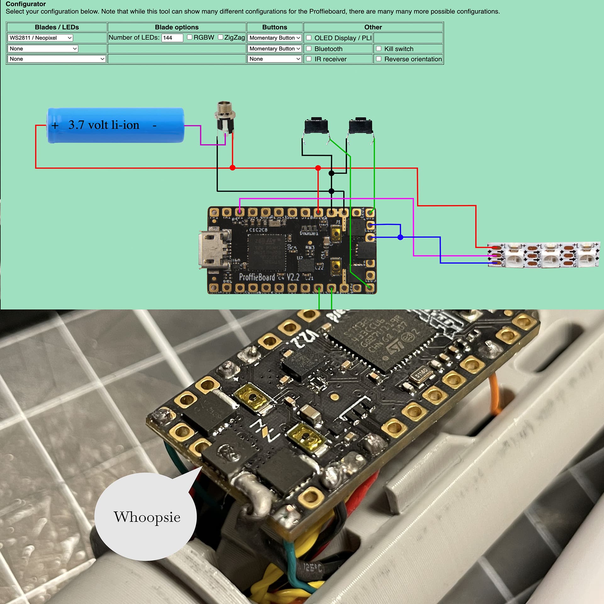
I’ve built my first lightsaber, a Graflex using proffieboard v2. It’s been a very rewarding process, but I’m still not done, since I’ve run in to some probblems. Only one half of my 2x127 strips ever lit up. I’ve connected them both back to back in the same tube - wired in parallell. After some further testing one of my mosfets gave up in a plume of smoke. Have I not wired this correctly using two power pins? Should I have doubled that since I’m using double blades? I’ve been following this wire diagram (Proffieboard V2)
In addition, I’m not sure how the kill switch really is intended to work. Because while this happened I wasn’t able to turn my saber off using the kill switch and now I wonder if I’ve wired it correctly.
I measure 4 volts up on my blade connector pogo pins even when the kill switch is off. I’ve followed the chart above and double checked my wiring but according to it the kill switch doesn’t even break the current to the leds. What should I make of this?
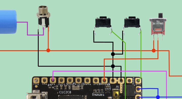
Your wiring diagram doesn’t include a Kill Switch. The kill switch controls the only path from Batt + to the Proffie board (image below)–unless you meant a kill-key on the charge port (and I cannot answer questions about that).
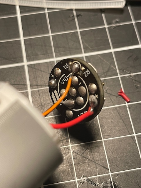
Two mosfets should be enough for two 127 pixel strips. Did you confirm that you didn’t have any shorts across your wiring with a multimeter? If only one blade lit up, I’d say definitely check the wiring on our blade-side PCB–make sure you didn’t cross the Pos and Neg.
Two LED pads should be enough.
You probably have a short somewhere causing you problems though.
For instance, the back of the two strips might be touching somewhere?
Since + lines up with - on the back, you would get bad juju if they touch.
Also, please make sure that you didn’t:
wire + to - when connecting the two strips together.
Wire one of the strips backwards. (There should be arrows that show the data direction.)
Your diagram doesn’t show a kill switch. However, it shows a charging port, so maybe you are talking about using a kill key together with your charging port?
So where did you put the negative lead when you measured?
Current can be interrupted on the way there, or on the way back, and the effect is basically the same. You should always have battery voltage at the blade, but the negative pins should be non-conductive, so no power will flow.
It’s also possible that your fried FETs are allowing current through when they aren’t supposed to, which would give the blade power all the time.
My bad on the Kill switch, I simply screenshot the wrong diagram. My wiring is according to the diagram you posted, and like you said it seems only to control the path from Battery to Proffie board. Was just wondering why this is the case?
But perhaps you’re right in that the fried FETs have altered something.
These are good hints, I’ll go back and make sure I didn’t do that. The strips themselves are taped with some double sided tape so no conductors ought to be touching but I’ll double check the ends. I did measure conductivity between + and + on both strips, aswell as between - and -, but will have to double check for shorts on the blade side pcb aswell as direction.
About the config file, am I right in assuming I should still use 127 like this since the two strips are wired in parallell?
Even if it didn’t measuring the voltage can be misleading, because if the FETs are turned off, then the negative pins are basically floating, which means that you can get odd measurements.
That is correct.
Yes, that should work unless something else also got damaged.
Have made some measurements now, and I can confirm I don’t seem to have any short circuits in my blade. Arrows both point towards the end, back sides of tape has nothing conductive and there is No continuity between + and -. Measured at the tip however there is continuity between + and + on both strips (aswell as -)
The hilt side pcb however tested in an odd way, and I can’t get my head around it really. When I measure the back of it where I’ve soldered, + is isolated from -. But when I check continuity on the pogo pins current flows all over, + to - and data.
Active electronics (like neopixels) can in some cases measure as continuity.
Depending on how your multimeter works, they can measure as continuity one way, but not the other way. Maybe that’s what’s happening here?
That might be just the thing, because after testing again both the pogo side and solder side of the pcb behaves like this:
If I put red probe on + and black on - no continuity is read.
If I do them opposite, continuity is detected.
So your saying this could be fine, not an indication of a short, and would possibly read no continuity either way if battery was not part of the circuit?