After seeing @mcarcher 's testing station / base I was inspired to sort out a proper one for myself.
seeing my last set up was more a bodge it and leg it affair
so I did some searching on the net and on Ebay.
all components were sourced from Ebay in the end as the prices were very good.
I think I must have spent about £12 in total but I will have to add it up properly a bit later.
but all components were easy to find and I will link the sellers after some sleep.
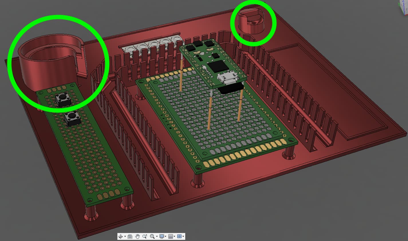
the main thing I wanted to achieve was to have a complete station hat had the all components on it without being too big, so I got on the laptop and cam up with this.
it has spaces for battery, switch board, main board (proffie), crystal chamber holder, strip of 5 pixels to simulate blade pixel board and holder for a short pixel strip to simulate the main blade.
I added a channel with slots in to keep the wiring neater and may add a lid to it later if required.
its currently printing and I’ll post up what it looks like when its finished.
please feel free to put up what your set up looks like.
I highly recommend using two boards to hold the pins. Maybe that’s already the idea? (The boards should be maybe 1cm apart or more to make sure the pins are held straight.)
What are these?
I could see it being cool/convenient to have a pogo blade PCB mounted in the bottom of that left thing to insert a blade vertically for testing.
The one on the left is probably for holding a speaker. Not sure about the other one.
I do see now that they are two boards, but it looks like they are really close to each other?
A bit like this.
The strip of 5 pixels will serve as a sudo blade connector.
The speaker part i wanted to keep separate as it will most likely be the main source of testing.
So long flying leads and plenty of 3d printing.
I did 2 boards back to back and seem to hold the pins very well.
If I have problems with them then I will remove them and space the boards a bit.
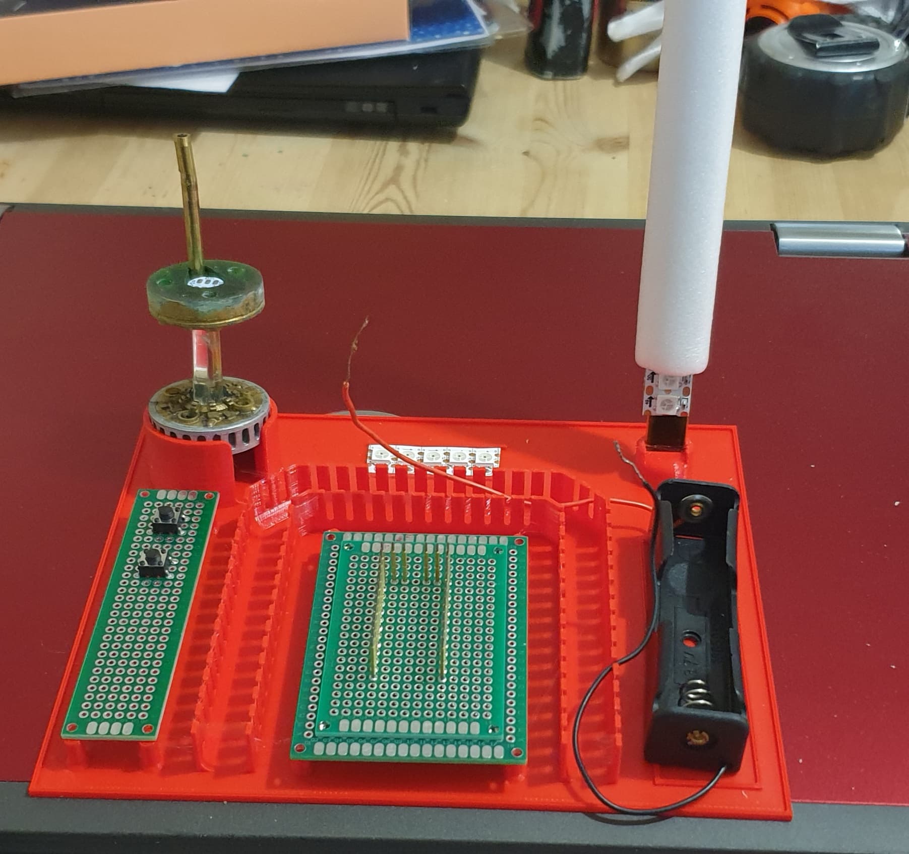
the strips are stuck on a flat piece of carbon fibre. (the carbon fibre is wrapped in Kapton tape)
I will solder the wires on the bottom of the strips a bit later.
just thought, why do I need to lay the strips down? and as I has some carbon strip left I thought id use it up.
Looking good there! I’m sensing some industrial wiring experience looking at the wire channels you modeled. It’s so much more professional than mine!
A couple notes:
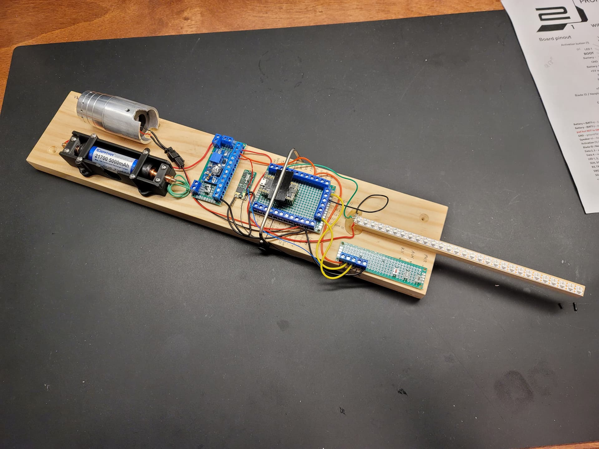
It may be too late, but I would really suggest making the while thing narrow and longer. The reason I made mine on a board is so that I can swing it around and really test the gestures and movements:
You might want to make the blade a bit longer, since with only 5 pixels you won’t really be able to see any blaster or foc colors that well.
I would really recommend using screw terminals for the proffieboard, as it will let you change things faster. You may already be planning on doing this. I also labeled the wood next to the board to show what pins are which:
Why thank you and you are correct, I did quite a few years doing industrial installs.
The 5 pixels is for the sudo shtoky blade connector.
The funky stick on the right is the main blade and has about 40 pixels.
I see what you mean with the size part but for now I’m only interested in the basics.
I was going to use jst connectors for the most common componants I want to quick change, the rest will be screw down terminals.
But it may change.
That board is a breakout for the battery. So there are 4 negative and 4 positive screw terminals.
The circuit on the board is a small boost converter I got on ebay a while back that can take the battery voltage and adjustibly boost it up to 30V. However, I didn’t look at the minimum driving voltage for the converter, so it ended up not working and I took it off. I mainly just put it on there for driving other projects if needed, since I don’t have a benchtop power supply.
Oh, and I also wired a kill switch and status led on the battery board, so I don’t have to take the battery out to cut power.
The battery holder is custom made because the stock ones don’t hold protected cells, and it has latches to keep the battery in when swinging the test stand around. I can send you the stl files for it if you want it.
Update for my station has seen some wiring done.
Along with some extra components for ease of use.
Had to stop there as I’ve run out of solder and waiting on my terminals to turn up but its mostly there.
For the life of me I can’t remember now, I did put it in for a reason though let me get back to you on that…
In the mean time I will leaving it open for guessing…
yes do, it will help you in testing and making sure the boards are fully working before an install.
I’ve not played with breadboards since school so cant remember fully how they work.
i think that (if memory serves well) they have lines that are connected so the holes that line up along that track will offer multiple points to connect components?


 let me get back to you on that…