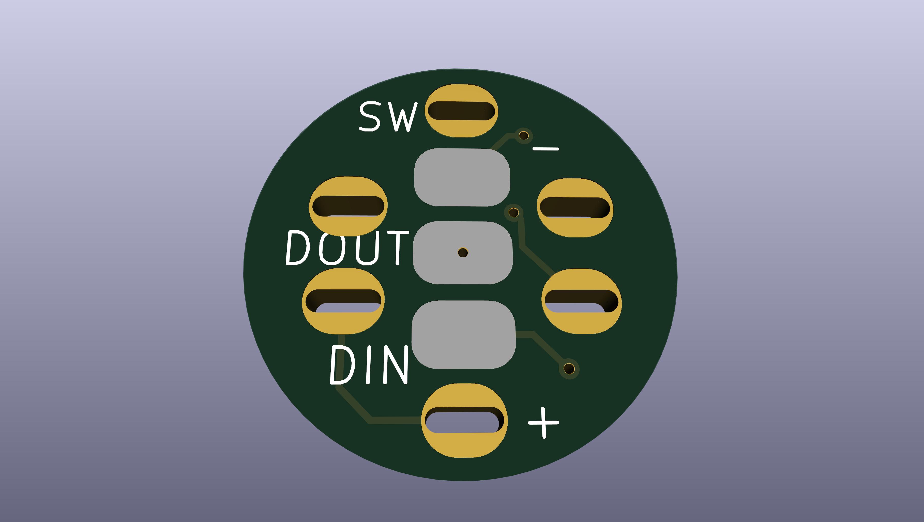
It’s 13mm in diameter, and fits on the back of a 16-mm AV button with an common-anode RGB led inside it. On the other side of the board, there will be a WS2811 chip and a data resistor.
I will post progress in this thread, which I hope will end with a run.
This PCB will assume that the legs are in a particular order.
The switches I have are all +/R/G/B, so hopefully that is what most switches do.
I have not seen any RGB 12mm switches, do you have a link for one?
Also, the chip I’m using will probably not fit between the legs of a 12mm switch, so it might be difficult.
If anybody has a 16mm RGB switch, can you measure the space between the switch contacts? My datasheet says it’s supposed to be 9.8mm, but the actual switch I have measures 9.5mm.
The prototype I’m working on works either way, but the tabs require a little bending to fit…
which type? I have a 16mm RGB common anode. Which internal space between the switch contacts is 8.5mm, post is 0.5mm thick so taking that into account, from outer side of each prong I get 9.5mm +/- 0.2mm
Well, I mean there are pixel style ones that would obviously have a different layout for the pins. Though they aren’t as common now since the KR ones made it to market.
I made the switchback have 9.6mm between the holes.
That means that some switches might need to have their terminals bent slightly to fit, but I think it should work.