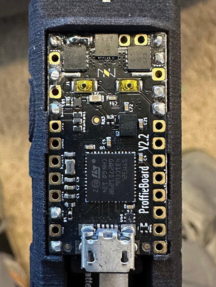
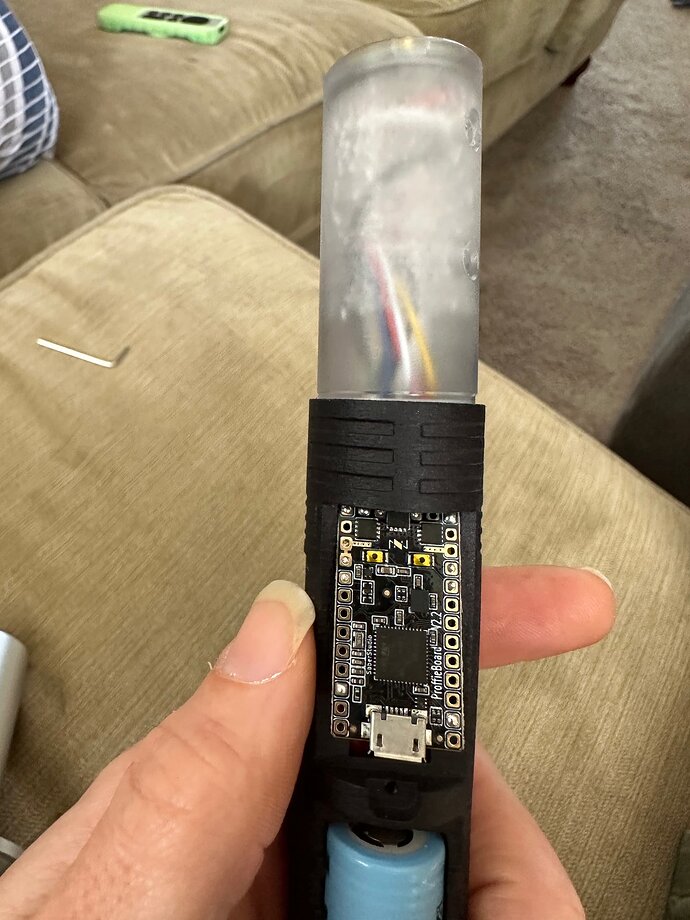
I have a couple sabers (look like they are from the same manufacturer) that both had the LEDs in the pommel stop working after editing the board with the config included on the saber’s sd card. does anyone see anything that stands out in the config why they wouldn’t be working? thanks.
The config simply doesn’t match how your saber is wired.
It states there are two blades:
- Using bladePin with 128 LEDs using LED2, and LED3, and
- Using blade2Pin with 128 LEDs using LED4, and LED5
However, your proffieboard, based on the image is wired with two blades:
- Using bladePin with [Depends on Blade Length] LEDs using LED2, and LED3, and
- Using blade4Pin with [Unknown] LEDs using LED6
Start by editing your config to change that second blade so it matches, then I’d recommend using LengthFinder<> to figure out how many LEDs are there.
the pommel leds are clearly visible. there are three of them. is that the same? are these defines at the very end of the config after the blade style? is that the only part I need to change? this part:
BladeConfig blades = {
{ 0, WS281XBladePtr<128, bladePin, Color8::GRB, PowerPINS<bladePowerPin2, bladePowerPin3> >(),
WS281XBladePtr<30, blade2Pin, Color8::GRB, PowerPINS<bladePowerPin4, bladePowerPin5> >()
, CONFIGARRAY(presets) },
};
if so, what do I need to change it to, if you don’t mind? thanks for your help. it looks like the second blade is indicated as blade2pin. that should be 4? I also probably should know the difference between bladepins and bladepowerpins, I’m guessing. smh.
Quick Note: Format your code by using 3 backticks before and after like this:
```
[CODE]
```
There’s two parts to blade config, but yes, that’s the bulk of it. The other part (that you don’t need to change in this case, since it’s the same number) is the #define NUM_BLADES
So, the first number after the WS281XBladePtr is the number of LEDs in the blade (128 and 30, respectively, is what’s set in your code snippet), then the next pin is the pin for data, then the color order, then the power pins to use.
If you know there’s 3 LEDs on the accent then you’d change the number for the second blade to 3.
Correct, blade4Pin/Data4 is the data being used for the second blade.
blade#Pins are the pins used for sending the actual neopixel data signal, whereas bladePowerPin#s are the LED# pads which are used to turn the LEDs completely on or off (Since neopixels still drain quite a bit of power even when they’re set to Black, completely cutting power is necessary), those are the pins that control the MOSFETs (the black squares near the back of the board)
Official Reference:
I can’t believe how kind and willing people are to help on here. Seriously, thank you.
So, from what you’re seeing, all I need to do is change the 30 in the second blade to a 3, and change the blade2pin to blade4pin?
Is that all, or do I need to adjust the power pin settings as well?
Mostly, yeah.
You’ll need to change the PowerPINS<bladePowerPin4, bladePowerPin5> to PowerPINS<bladePowerPin6> too, otherwise the correct MOSFET won’t be turned on when the LED is supposed to light up.
P.S. No problem, this stuff’s easily confusing, especially if you’re new to it ![]()
You’re the best. I’ll give it a shot as soon as I get back. Go treat yourself today for helping a stranger ![]() .
.
so, I tried that without any luck. could be I entered something in wrong. would you mind taking a look and seeing if I am missing something? thanks.
The power pins are still set to 4 and 5, so the accent won’t be getting any power.
Oh Dangit. I must have copied and pasted the wrong config. I had like five open on my desktop. I did try to change the power pin to 6. I wonder if I was missing a bracket or something. Back out again now. I’ll post the right one when I get back. Seriously, thanks again for your time.
No problem, lmk how it goes.
here it is:
Yep, that looks correct. Is that not working for you?
Bummer. No, it’s not. Everything works fine, just no LEDs. I do have a second saber that had the same problem. I may try to upload to that one just to rule out a disconnected wire or something on this one. Not sure what else to try.
never mind! you did it! thank you master ryryog ![]() . I’m an idiot. when I saved the updated file earlier, I saved it in my main saber files folder, not the proffie os folder. you’re awesome! thank you! this totally made my day.
. I’m an idiot. when I saved the updated file earlier, I saved it in my main saber files folder, not the proffie os folder. you’re awesome! thank you! this totally made my day.
Gotcha, awesome to hear! Have fun saber-ing ![]()
Just did it to the second one, and it worked on that one, too! It’s so exciting when you find the solution and actually get it to do what you want it to! ![]() . Thanks again. You fixed two of my sabers today.
. Thanks again. You fixed two of my sabers today.
had the same issue with another saber and pommel leds not labeled correctly in the attached config. can you tell from the board what pins the leds are on? here is the board:
and here is the config:
You got something going on with LED 4 and data 2.

