@profezzorn I’m just now retaking this project, and would like to use low power switches. I have the V2 pFET boards you designed when the low power feature of V3.9 turned out to be flawed. And I’ve found the MMBF4391 pFETs availables in my country. Would they work?
PN4391-93, MMBF4391-93.pdf (282.2 KB)
No, the gate-source cutoff voltage is -4 volts (typical), which is way too high.
The 4393 might work though.
You want the cutoff voltage to be between 0 and -1.5 volts basically.
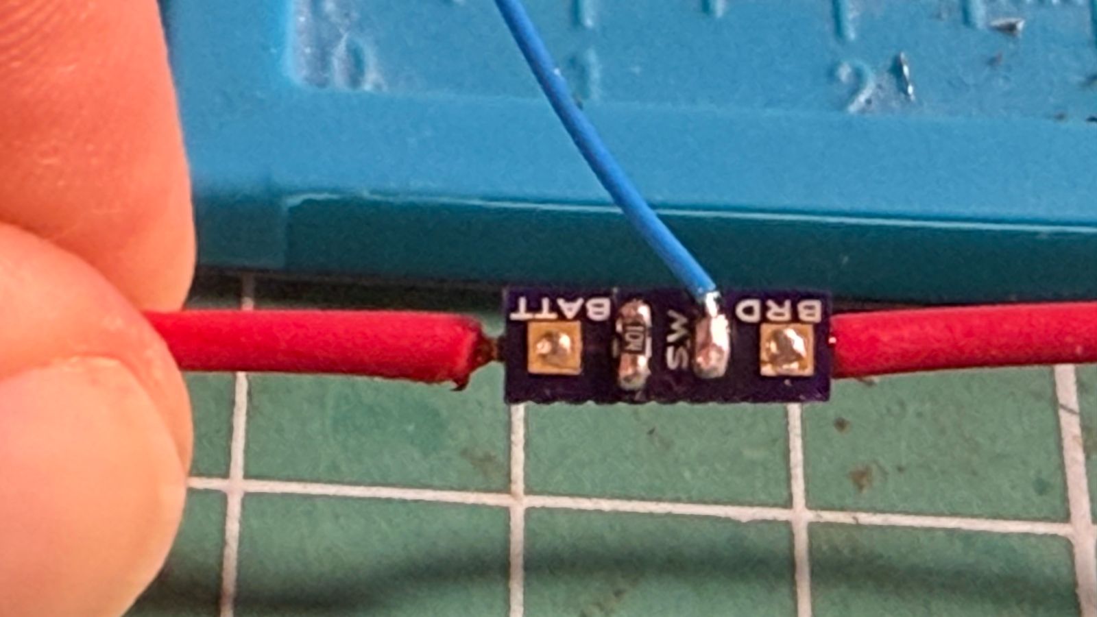
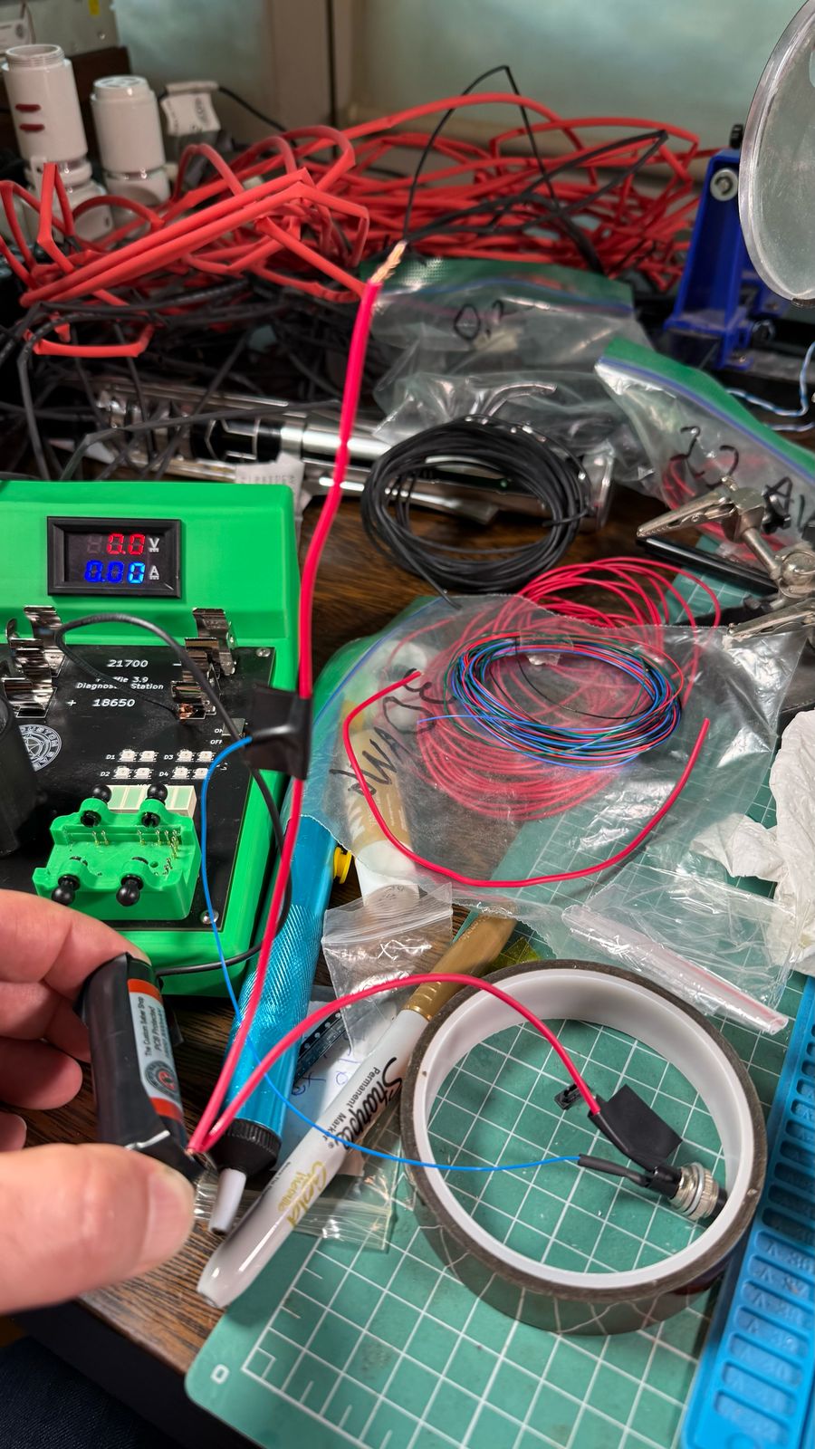
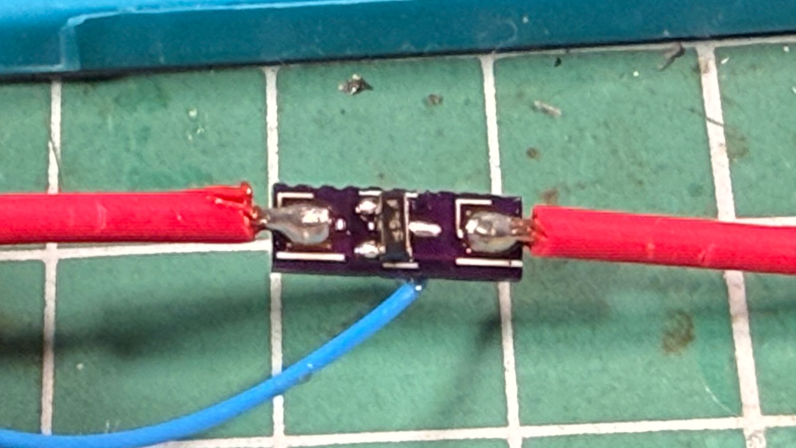
Yep, I checked that. I actually mistyped and was talking about the 4393. For practical purposes, I have a somewhat limited testing station. Can I test it by using the pFET board by putting it between the battery and the battery contacts to the testing station?
I would use a solderless breadboard for testing.
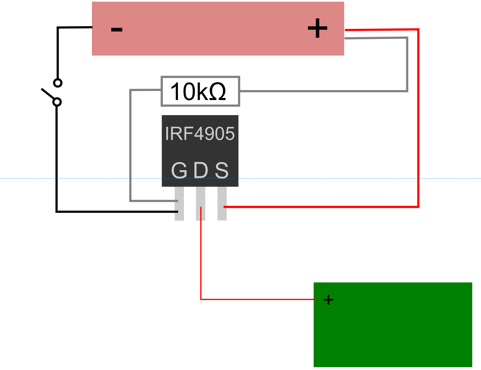
Basically, what you need is to hook it up like:
+----BATTERY+--+---FET-------+
|              |    |        |
|           switch--+        R
|              |             |
+--------------+-multimeter--+
R is a resistor, with a smallish value, say 100 ohm or so.
The multimeter should be set to current measurements.
When the switch is on, you should see battery voltage / R amperes through the circuit.
When the switch is off, you should see ZERO current through the circuit.
In the final setup, the proffieboard takes the place of the resistor and multimeter.
The 100R is in addition to the 100k smd on the board, right?
Yeah, the resistor on the board is hooked up to the gate to keep it off by default.
It’s not actually needed if you have the switch wired like I showed.
WIth the resistor you the switch-to-+ wire can be eliminated.
Perfect. I’m receiving the pFETs on the 21st. I guess that weekend I will make the test and post the results. Thanks!
I think we both forgot to check that the pins are in the same order.
The pFET I normally ( DMG2301L-7 ) has the pins like this:
DMG2301L-7
  D
[===]
G   S
While the one you have looks like this:
MMBF4393
  G
[===]
D   S
It says in the data sheet that drain and source are interchangeable, so you might be able to get it work by rotating the fet 120 degrees counter-clockwise, sort of like this:
MMBF4393
  ,S
 \\
G`\\_D
(I have done this on another circuit board which I designed with fet pins in the wrong order, so it is possible.)
I’ve tried to use it in that configuration and it didn’t work. Can I use an IGBT, specifically a model BTS 141 ( D2pak packaging)?
If so, do I still need a 100k resistor between gate and collector?
Looks like it should work.
You either need a pullup resistor, or connect the switch to + AND - and have the middle pin connected to the gate.
I will try the pullup resistor first. A 100k R should do it, right?
It looks correct to me, but be warned, I have mixed up source and drain more times than I can count…