Hi again,
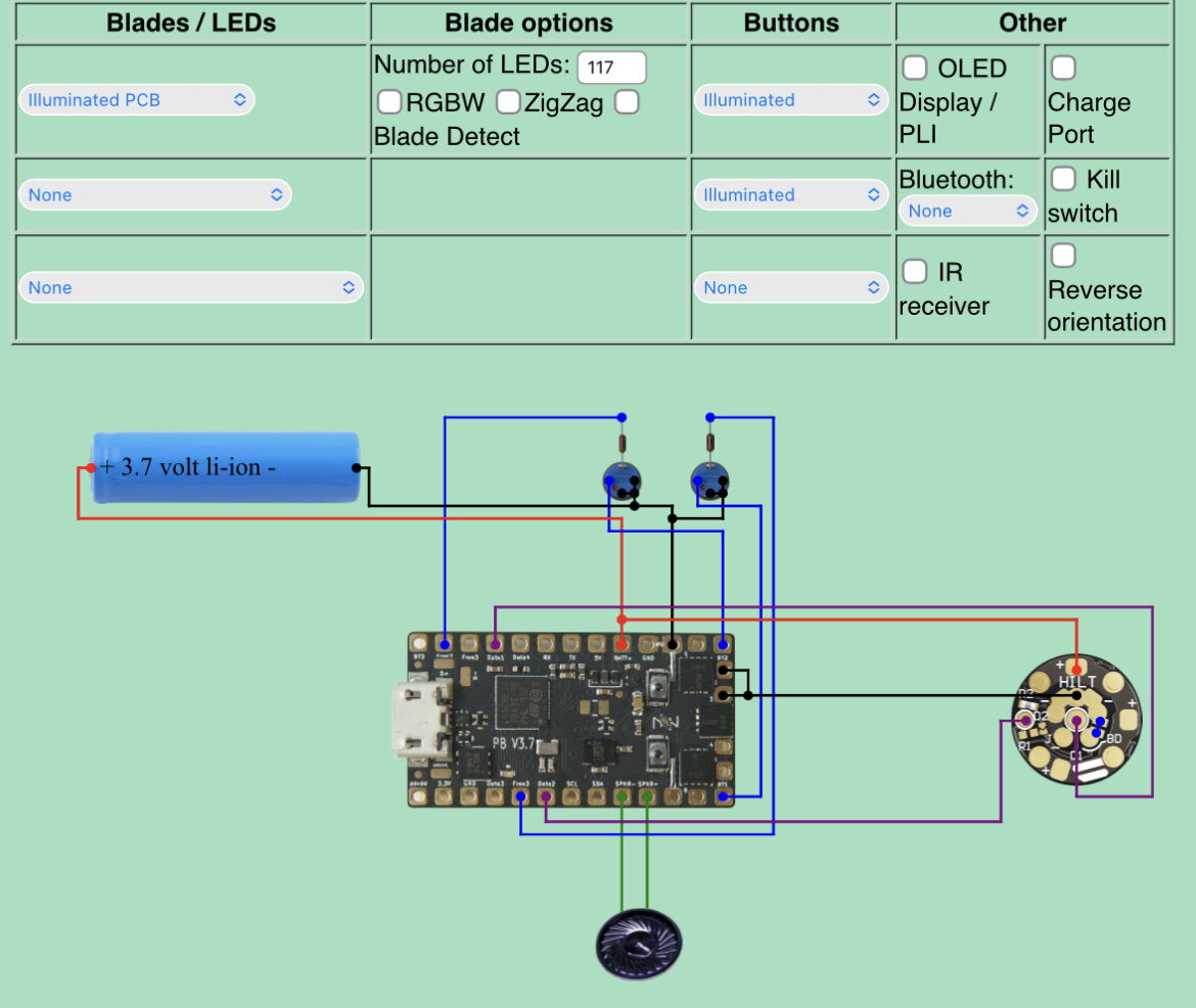
Here is what the config generator shows with my wiring selections.
Questions on the PCB:
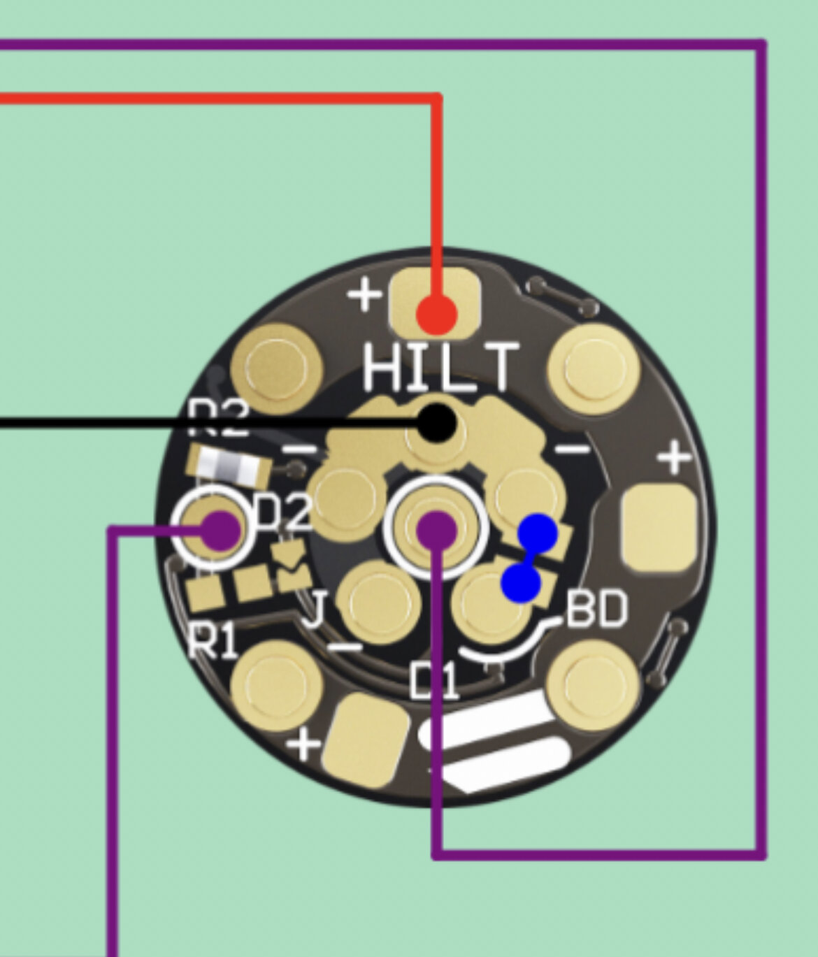
Am I soldering exactly where this picture shows; the negative shows it soldered on the middle PIN in between the 2 negative pads?
Also, the small blue dots show me bridge soldering the blade detect to the negative?
Thanks for any clarification on this!
I don’t see a need to solder the Blade Detect pin. If you use Shtok’s excellent V3, each pin can carry a peak of 5A. You will notice that the positive pins are four and the negative circle is five, exactly because the Blade Detect pin is not used for negative. So keep it that way.
Also, for having a separate data line for the illuminated PCB, make sure the R1 resistor is not present.
And last, don’t solder to the negative’s pin. Use the two squares on the side of the marked pin.
Thanks for helping.
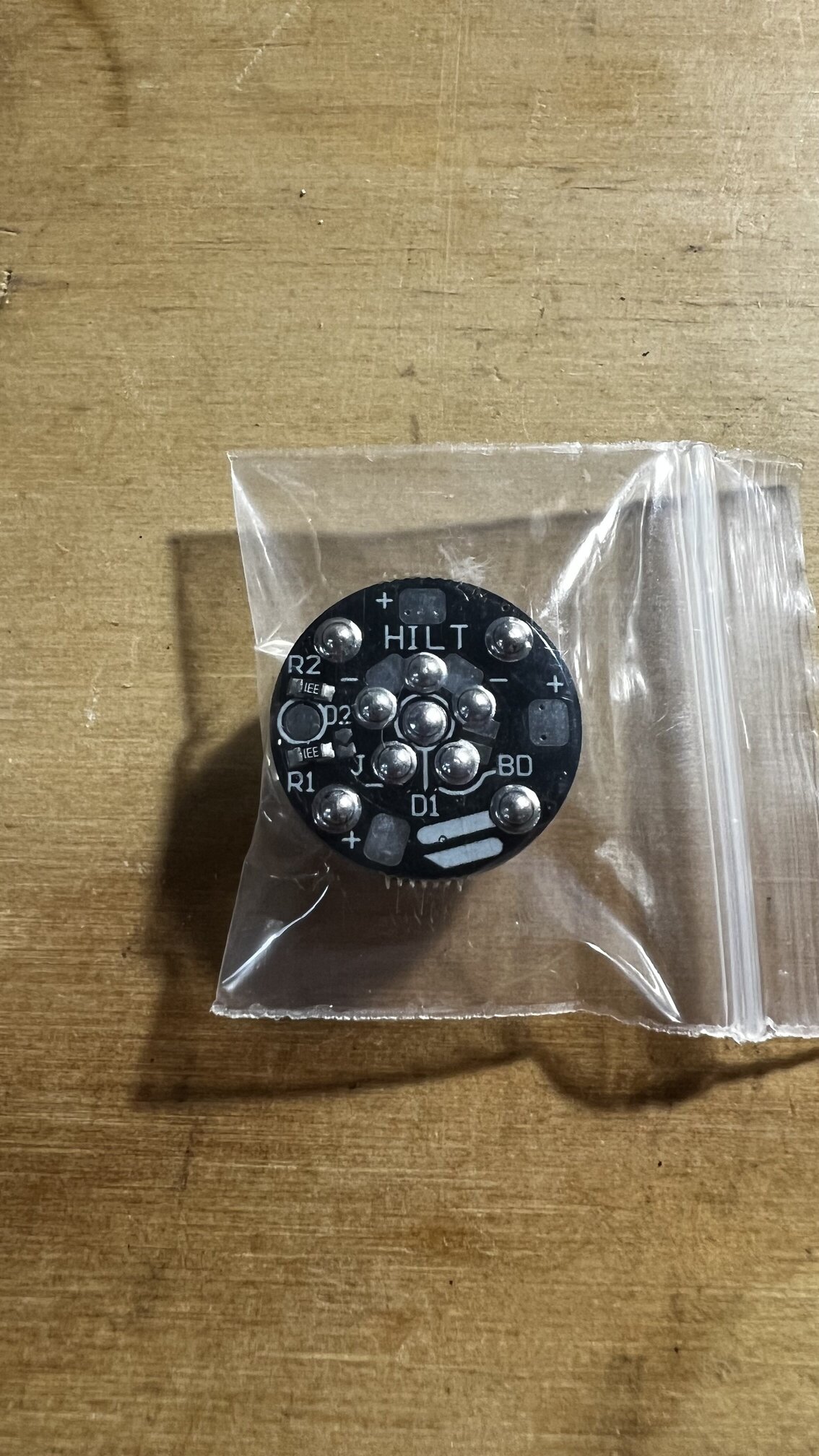
I am using a TCSS PCB and I do see the R1 resistor:
How does that change my connections?
You are indeed using a Shtok CustomWorx Illuminated PCB V3, acquired at TCSS.
Here you have some options depending on the level of customization that you want.
Positive goes to the external pads, and negative goes to the pads I told you before every single time.
Now your options: a neopixel is a strip of pixels. So, you can configure the PCB in three ways:
- The PCB pixels copy the first 16 pixels of your blade. You will have a single blade. You do not touch the PCB, put
WS2812 / Neopixel instead of Illuminated PCB and connect data1 to the D2 pad (the one on the side between the two resistors).
- The PCB pixels go in the same “strip” but before your blade’s pixel. You can add 16pixels to your config, or use subblade for a second blade. You loose the capability of doing Blade ID and identifying the
NO BLADE case. You will have to configure for WS2812 / Neopixel, write the subblades yourself. You would have to remove R1 resistor and bridge the J pads.
- The PCB pixels use a different data line and you treat them as a different blade. This is how the configurator is set. You have two blades (or three if you use subblades to differentiate inner and outer pixels). You will have to remove the R1 resistor.
You can also solder the negative wires here. You can solder behind the pin (no other choice in the center pin), but if you do it can cause the pin to become de-soldered.
Thanks for the breakdown!
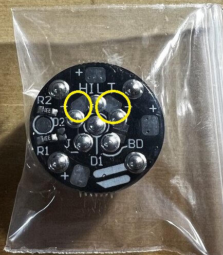
I will go with option 3 and remove the R1 resistor BUT; should I bridge BD as shown from the original configuration image?
Also, what is considered “best practices”:
Stand alone positive wire from battery to the + on PCB?
Or
Tap into the positive wire from battery that runs to the Proffieboard Batt+ pad?
I am using 20 gauge PTFE for that.
Bridging BD is entirely optional.
It makes the pogo pin board slightly better at carrying current, but unless you have a particularly power-hungry blade (like a quadblade) it probably doesn’t matter.
As long as the guage is big enough, it doesn’t matter. Do what makes most sense for your installation.
1 Like
Thanks for weighing in Prof!
I do have a quad blade so I will bridge BD!
That is why you are the supreme leader!