TL;DR I have a single button saber with Proffie V3 board but do not have original config.h file
if anything in my post has been answered already my apologies. As stated I cannot get the config.h file for my saber from original installer and would instead like to recreate this on my own. I read that boards have unique wiring and I would need to know this info in order to successfully make a config file but is there a way to figure this out just by looking at the board?
my progress so far: read through parts of ProffieOS documentation, can “talk” to my board via Arduino IDE, backedup SD card to local computer, backed up proffieboard to to local computer.
You would need to figure out what each wire connected to the board does.
Most of the time this is easy, because button wires are hooked up to button, data wires are hooked up to neopixels etc. but but sometimes the wiring gets creative, and then you have to actually check where each wire goes to figure it out.
Also, if you know that something goes to a button, but you don’t know which button, you can use the serial monitor to figure things out.
I also recommend backing up the actual program that’s on the board. Instructions here:
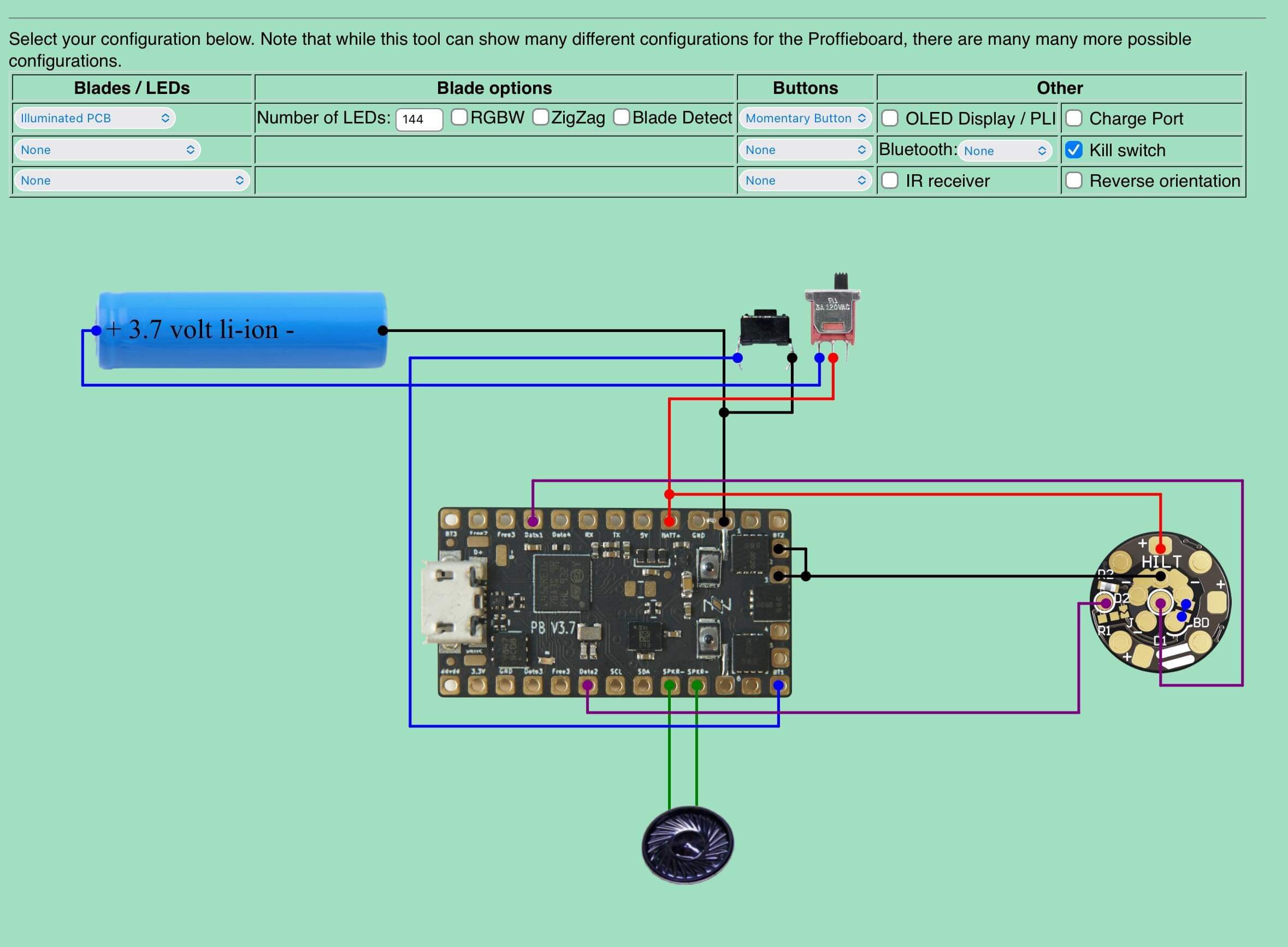
Thank you that seemed to do the trick. Judging from what my saber can do I feel confident this image is correct. My only question is that in the config file NUM_BLADES is shown as 3 but in the configurator i think i set it to 1?
Well, it depends on what kind of pogo pin PCB you have, and how it’s wired.
The configuration generator assumes a ShtokD PCB with two rings of LEDs on it. It has a separate data line (data2) for the pixels on the pogo pin PCB, and it uses subbbladewithstride to split the two circles into two separate “blades”. (A “blade” is just any row of LEDs here.)
Note that the ShtokD manual comes with descriptions for four different ways to wire the pogo pin PCB, so it could be wired differently. (Assuming your pogo pin PCB is even a ShtokD PCB)
The good news is that if you get some of these details wrong, nothing harmful will happen. It won’t work right, but if you did the backup I recommended earlier, then you can always go back again.
When you look at the board, check which data pins are soldered. That will give you some insight into how the board is wired, as Profezzorn said, you could have PCB pixels wired independently or in parallel. When I was reverse engineering my Proffie, I set each “blade” to a different color so I could see which data pin went where. That helped me trace the RGB pixels on the chassis buttons that were inside the handle and not visible unless the chassis was removed.
One thing to be aware of is that some neopixels use different byte orders, so there are cases when a blade comes out a different color than expected. Also, it comes out rainbow colored, then you have the number of bytes wrong, (RGB vs. RGBW)
I suggest starting with 2. If there isn’t a second blade, no harm no foul–if your blade pcb is in parallel or in series with the blade, it will all be the same color, but if it is wired independently, it will light up differently. Be sure to add extra pixels for the main blade just to be sure.
Do you know anything more about the saber–who made the hilt and who did the install (was it factory installed or privately)? Unless it was truly custom, like the Adam Savage special, someone here might be familiar with it and could give more insight.