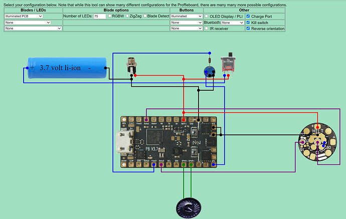
As the topic states, I just finished soldering a lightsaber with the following diagram and config:
Config
#include "proffieboard_v3_config.h"
#define NUM_BLADES 4
#define NUM_BUTTONS 1
#define VOLUME 1000
const unsigned int maxLedsPerStrip = 144;
#define CLASH_THRESHOLD_G 1.0
#define ENABLE_AUDIO
#define ENABLE_MOTION
#define ENABLE_WS2811
#define ENABLE_SD
#define ORIENTATION ORIENTATION_USB_TOWARDS_BLADE
#define SHARED_POWER_PINS
#endif

#ifdef CONFIG_PRESETS
Preset presets[] = {
   { "TeensySF", "tracks/venus.wav",
    StyleNormalPtr<CYAN, WHITE, 300, 800>(),
    StyleNormalPtr<CYAN, WHITE, 300, 800>(),
    StyleNormalPtr<CYAN, WHITE, 300, 800>(),
    StyleNormalPtr<CYAN, WHITE, 300, 800>(), "cyan"},
   { "SmthJedi", "tracks/mars.wav",
    StylePtr<InOutSparkTip<EASYBLADE(BLUE, WHITE), 300, 800> >(),
    StylePtr<InOutSparkTip<EASYBLADE(BLUE, WHITE), 300, 800> >(),
    StylePtr<InOutSparkTip<EASYBLADE(BLUE, WHITE), 300, 800> >(),
    StylePtr<InOutSparkTip<EASYBLADE(BLUE, WHITE), 300, 800> >(), "blue"},
   { "SmthGrey", "tracks/mercury.wav",
    StyleFirePtr<RED, YELLOW, 0>(),
    StyleFirePtr<RED, YELLOW, 1>(),
    StyleFirePtr<RED, YELLOW, 2>(),
    StyleFirePtr<RED, YELLOW, 3>(), "fire"},
   { "SmthFuzz", "tracks/uranus.wav",
    StyleNormalPtr<RED, WHITE, 300, 800>(),
    StyleNormalPtr<RED, WHITE, 300, 800>(),
    StyleNormalPtr<RED, WHITE, 300, 800>(),
    StyleNormalPtr<RED, WHITE, 300, 800>(), "red"},
   { "RgueCmdr", "tracks/venus.wav",
    StyleFirePtr<BLUE, CYAN, 0>(),
    StyleFirePtr<BLUE, CYAN, 1>(),
    StyleFirePtr<BLUE, CYAN, 2>(),
    StyleFirePtr<BLUE, CYAN, 3>(), "blue fire"},
   { "TthCrstl", "tracks/mars.wav",
    StylePtr<InOutHelper<EASYBLADE(OnSpark<GREEN>, WHITE), 300, 800> >(),
    StylePtr<InOutHelper<EASYBLADE(OnSpark<GREEN>, WHITE), 300, 800> >(),
    StylePtr<InOutHelper<EASYBLADE(OnSpark<GREEN>, WHITE), 300, 800> >(),
    StylePtr<InOutHelper<EASYBLADE(OnSpark<GREEN>, WHITE), 300, 800> >(), "green"},
   { "TeensySF", "tracks/mercury.wav",
    StyleNormalPtr<WHITE, RED, 300, 800, RED>(),
    StyleNormalPtr<WHITE, RED, 300, 800, RED>(),
    StyleNormalPtr<WHITE, RED, 300, 800, RED>(),
    StyleNormalPtr<WHITE, RED, 300, 800, RED>(), "white"},
   { "SmthJedi", "tracks/uranus.wav",
    StyleNormalPtr<AudioFlicker<YELLOW, WHITE>, BLUE, 300, 800>(),
    StyleNormalPtr<AudioFlicker<YELLOW, WHITE>, BLUE, 300, 800>(),
    StyleNormalPtr<AudioFlicker<YELLOW, WHITE>, BLUE, 300, 800>(),
    StyleNormalPtr<AudioFlicker<YELLOW, WHITE>, BLUE, 300, 800>(), "yellow"},
   { "SmthGrey", "tracks/venus.wav",
    StylePtr<InOutSparkTip<EASYBLADE(MAGENTA, WHITE), 300, 800> >(),
    StylePtr<InOutSparkTip<EASYBLADE(MAGENTA, WHITE), 300, 800> >(),
    StylePtr<InOutSparkTip<EASYBLADE(MAGENTA, WHITE), 300, 800> >(),
    StylePtr<InOutSparkTip<EASYBLADE(MAGENTA, WHITE), 300, 800> >(), "magenta"},
   { "SmthFuzz", "tracks/mars.wav",
    StyleNormalPtr<Gradient<RED, BLUE>, Gradient<CYAN, YELLOW>, 300, 800>(),
    StyleNormalPtr<Gradient<RED, BLUE>, Gradient<CYAN, YELLOW>, 300, 800>(),
    StyleNormalPtr<Gradient<RED, BLUE>, Gradient<CYAN, YELLOW>, 300, 800>(),
    StyleNormalPtr<Gradient<RED, BLUE>, Gradient<CYAN, YELLOW>, 300, 800>(), "gradient"},
   { "RgueCmdr", "tracks/mercury.wav",
    StyleRainbowPtr<300, 800>(),
    StyleRainbowPtr<300, 800>(),
    StyleRainbowPtr<300, 800>(),
    StyleRainbowPtr<300, 800>(), "rainbow"},
   { "TthCrstl", "tracks/uranus.wav",
    StyleStrobePtr<WHITE, Rainbow, 15, 300, 800>(),
    StyleStrobePtr<WHITE, Rainbow, 15, 300, 800>(),
    StyleStrobePtr<WHITE, Rainbow, 15, 300, 800>(),
    StyleStrobePtr<WHITE, Rainbow, 15, 300, 800>(), "strobe"},
   { "TeensySF", "tracks/venus.wav",
    &style_pov,
    StyleNormalPtr<BLACK, BLACK, 300, 800>(),
    StyleNormalPtr<BLACK, BLACK, 300, 800>(),
    StyleNormalPtr<BLACK, BLACK, 300, 800>(), "POV"},
   { "SmthJedi", "tracks/mars.wav",
    &style_charging,
    StyleNormalPtr<BLACK, BLACK, 300, 800>(),
    StyleNormalPtr<BLACK, BLACK, 300, 800>(),
    StyleNormalPtr<BLACK, BLACK, 300, 800>(), "Battery\nLevel"}
};
BladeConfig blades[] = {
 { 0, WS281XBladePtr<80, bladePin, Color8::GRB, PowerPINS<bladePowerPin2, bladePowerPin3> >(),
    SubBladeWithStride(0, 15, 2, WS281XBladePtr<16, blade2Pin, Color8::GRB, PowerPINS<bladePowerPin2, bladePowerPin3> >()),
    SubBladeWithStride(1, 15, 2, NULL),
    SimpleBladePtr<CreeXPE2WhiteTemplate<550>, NoLED, NoLED, NoLED, blade5Pin, -1, -1, -1>()
  , CONFIGARRAY(presets) },
};
#endif

#ifdef CONFIG_BUTTONS
Button PowerButton(BUTTON_POWER, powerButtonPin, "pow");
#endif
The saber/soundboard powers on properly, but there are a few issues.
- The hilt side blade connector LED works properly.
- The blade does not light up at all.
- The illuminated switch turns on for a second and then goes out.
I’m thinking/hoping it’s configuration related issues?
First, I’m noticing that by Proffieboard V3.9 differs from the V3.7 in the above wiring diagram. I soldered the illuminated switch resistor to the contact next to Data2 (same location as pictured) which on my board is Free1 not Free3 as in the V3.7 pictured. Unless it’s just a typo on the board/picture? (I see two Free3’s.)
For the blade not working, I’m trying to check continuity… I used this kit: 1" BTF SK6812 Show Blade Builders Bundle. But strangely, I’m trying to check for the simple continuity on the blade connector (Pixel PCB - blade side) from the middle “D” pad to the center circle on the other side of PCB and I’m not getting anything? ![]() I kind of think that’s my issue, but idk how else I could wire it…seems very straight forward.
I kind of think that’s my issue, but idk how else I could wire it…seems very straight forward.
Other notes:
- On the hilt-side blade connector I wired/shorted the negative (-) and BD pads together as shown in the wiring diagram.
- There are two resistors on the hilt-side connector and one resistor on the blade side connector.
- The illuminated switch uses a 20mA DynaOhm™ Variable Resistor.
Ty
