I have a old (2018) Saberforge MPP MkII that I have been using for my 501st Vader and it recently died. Just nothing. Battery ended up being dead so I changed it out to a new battery of similar specs but it did not revive it. Checked all connections and tested power to switch, board, everything shows receiving but the Sabercore3 just doesn’t come to life.
I decided to upgrade the saber being I saw the configurator and not being well versed with programming, but good with wiring I figured I could do it between the two. I unsoldered the components from the old board, got a new charge circuit for usb C, a buckpuck to feed the LED vs the resistor and of course the Proffie 3.9. I got everything in last night and started to wire things up and hopped on the site to configure the Proffie… only problem is I can’t figure out what to select for the LED type since it is a single red CREE2 LED that is so embedded to the saber I can’t figure out for to take out. I wired it to the buckpuck to start, but it doesn’t help with the programming portion.
What do I select for this? Or is there anyone that can help me program this? Its a single switch with a single CREE2 LED.
I’m planning on buying and downloading a few different Vader fonts for it to see which I like best, so I know I would have to do the hold the switch while off and smack the blade to change those once this thing is alive, but as I said, programming isn’t my forte.
Just completely halted and I’m trying to resurrect this thing for July 12th. Help greatly appreciated!
I think you’ll just want to use a CH1LED for the LED, since the buckpuck will take care of the rest.
Thank you for the reply, I don’t see that option on the configuration site, or should I be using something else? I was going off of Proffieboard V3
Wait a minute…
What kind of buck puck are you using?
The one listed on TCSS requires a dual-battery input. However, proffieboards cannot accept input voltages higher than 5.5 volts.
So how is this going to be wired exactly?
It might be easier to just use a resistor instead of a buck puck.
I got this one (BuckPuck 1000mA 6-wire) which says min 5v max 32v input, its 1000ma so I figured it should be more than sufficient for it being powered off a 21700 5000mah lion battery.
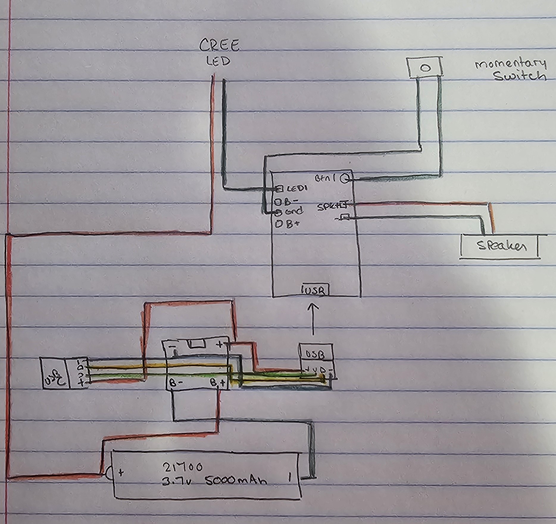
Planning on having a charge circuit with a USB C that goes to the charge board which is wired into the battery and then the other end to the Proffie. Speaker coming off the proper connections for that. Since I have the one momentary switch, I figured it goes to button 1 and ground. Then the buckpuck gets wired to the 5v and ground to feed the LED and the CREE2 takes the LED 1 slot and a ground connection as well.
At least that is what I am assuming will be needed.
I should also state that when I was thinking this, which didn’t come out, is a step up converter to go from the 3.7v from the battery to the 5v of the buck. Unless you think this is better served as just a resistor?
Almost certainly better served just using a resistor. Otherwise you’re stepping up to step right back down again, which is unnecessarily complicated (and expensive)
The 5v pad on the board does not have enough juice to power a buckpuck without affecting the sound quality. Also, as other people pointed out; doing a step-up and then a step-down will probably produce just as much heat as using a resistor, so it might not help the battery last any longer.
A separate step-up converter could work, but a resistor is going to be much smaller and simpler and probably work about as well in terms of battery life.
Okay, only thing I’ll have to try to figure out is what kind of resistor it’ll need since the original is unable to be removed and it was directly wired to the sabercore3 board without one.
Other than the obvious missing connection from battery to B+ and B- on the Proffie, quick sketch I just did of the wiring in case you want to look that over as well, but the biggest thing is the configuration since, once again, I’m a complete novice at it.
If it’s a CREE LED, those have known specifications.
TCSS has a resistor calculator that’s pretty easy to use, and has presets for certain LED types: LED Calculator
So with much experimenting, I managed to get something in configuration that looks to work. Despite being 1 cree, I used the tri CREE setup and just didn’t wire to LED 2/3 and decided to try running that config in Arduino. It installed with the setup and gave error 74 right after successful upload message. I decided to give it a try and finished wiring up the Proffie 3.9 to my electronics. Hit the button and had life!
Now time to replace the sound font to have Vader’s in there.