Kylo Ren Cross Guard - Need some help with 'Blade Detect' and little questions

Hi everyone,

I have been scratching my head a bit and Brian and Matthew have been great as usual in another forum but I thought I would come here too.

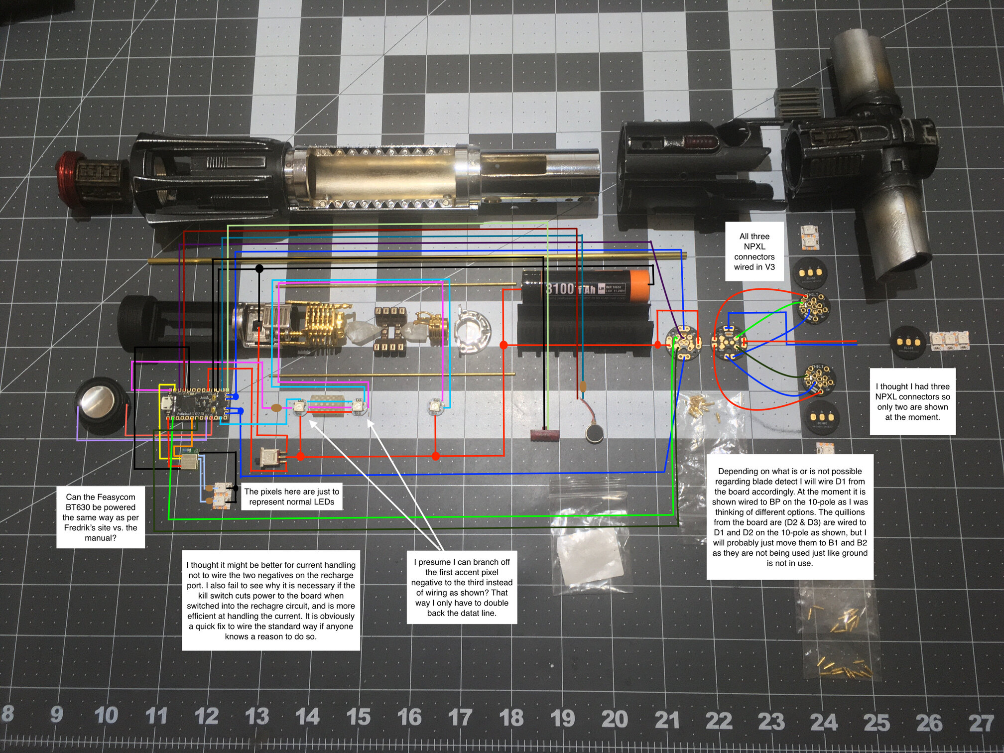
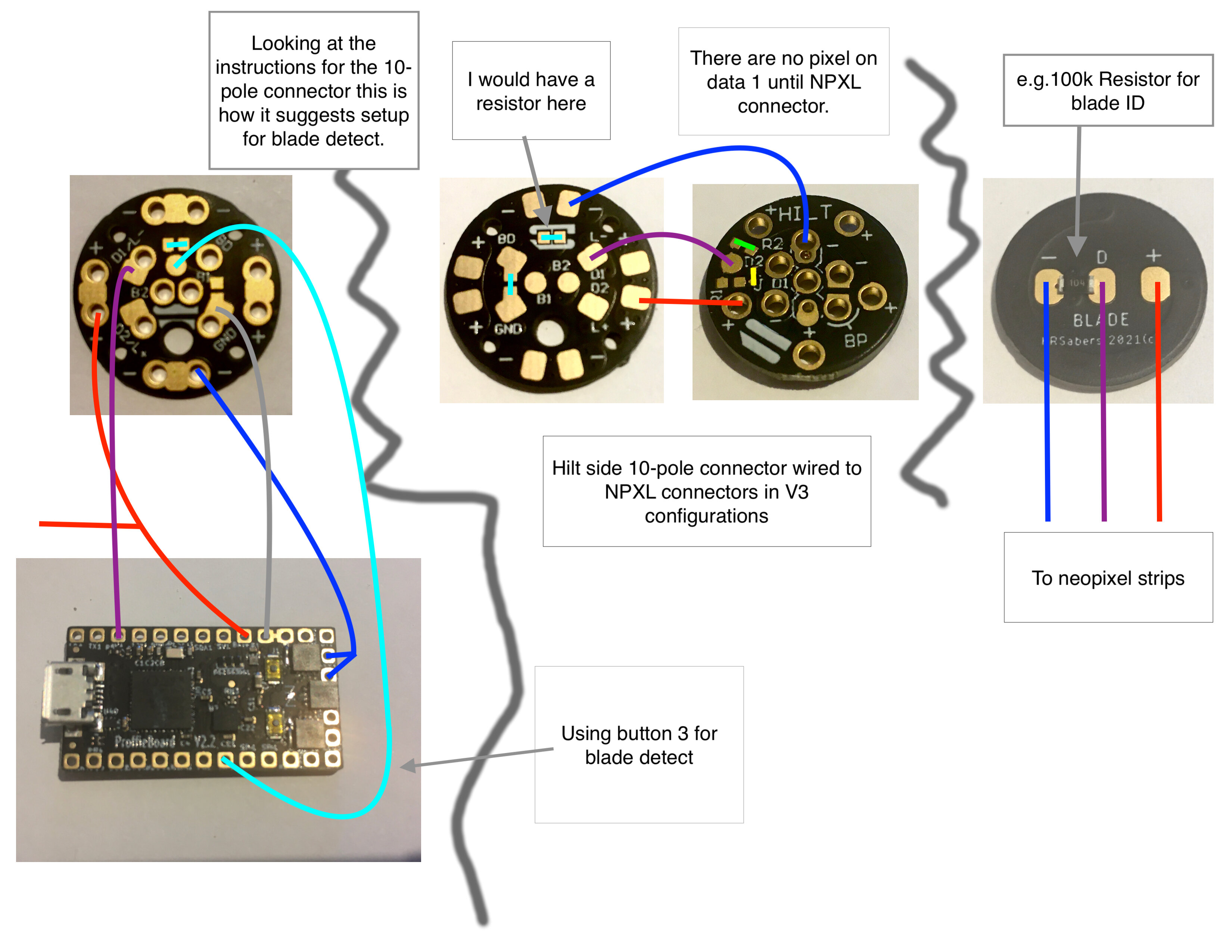
I am using Dmitry’s 10-pole indexed connector so I can have a removable chassis. I then have his NPXL connectors in a cross guard.

I want to be able to use ‘blade detect’ to setup up three different blade arrays;
#1 for just the chassis
#2 for when inserted to the hilt (10-pole connected)
#3 for when I insert the main blade only (planning on using the NPXL BP -ve to D1 short option).

I’m pretty sure this is possible and have looked at the three various setups in the Proffie manual and the 10-pole manual.

I think option A (page 21) can work somehow, but could use some guidance regarding

1/RT = 1/R1 + 1/R2 + 1/R3

I don’t know what the tolerance is for resistance values detected by the board so would be grateful for any input. My concern is using resistors that will give enough of a difference in values to allow for detecting three different blade configs with a good degree of accuracy.

Hopefully the picture diagram does not get compressed beyond comprehension. Please feel free to comment on any efficiencies etc., as it is a fair bit of wiring to hide; I have added a few small questions to my diagram too for which I welcome input.

Also just another option regarding the blade detect if it helps, you will notice I still have Aux2 Button 3 available. If the blade detect is not possible in the way I wish to use it, I will just have to make a tough choice.

Thanks in advance for any and all suggestions, I have been putting off this build for quite a while.

Drop box link in case of poor res:

https://www.dropbox.com/s/juk8xcn2listkn9/Kylo%20wiring%20diagram.jpg?dl=0

You can use anywhere from 2k-100k for resistor values, so since you only need 2 states other than NO_BLADE, something like 30k on the hilt 10pin PCB and another 30K in the blade would work.
The trick is that the blade detect thing only gets triggered to check the resistance when the blade detect pin gets grounded. You’ll need 2 blade detect pins then, one for the 10pin Hilt, one for the blade PCB.

That’s not too tough to do, but it does mean some modifications to a couple of system files.

P.S. I really like your real parts exploded view version of a wiring diagram, although a plain surface instead of the mat would likely be even better. I might borrow this for my next build!

1 Like

I think there is a bit of confusion between “blade detect” and “blade ID” here.
Blade ID uses extra resistors on the data pin to identify the blade. However, it is not able to detect if the blade changes. Blade Detect uses a separate line to detect when a blade is connected, but it does not use any resistors, so it only has two states “blade in” and “NO_BLADE”.

So, this leads to some options. Let’s start with the ones that don’t require any ProffieOS modifications:

  1. Just use Blade ID. This means putting one resistor in the hilt and one in the blade. Something in the 10-50k range would work for each. And you would use the \frac{1}{1/R1 + 1/R2} to calculate the total resistance. PROS: no extra wires, no coding CONS: does not detect when hilt or blade is removed, you have to switch power on and off and of for it to re-detect what is connected.

  2. Use blade detect for the chassis and blade ID for the blade. This means sacrificing some pins on the 6-pad connector for blade detect. We don’t need an ID resistor in the hilt, just in the blade. PROS: no coding, sound effect when chasis is inserted/removed, CONS: no effect when blade is inserted/removed

  3. Use blade detect for both blade and chassis. Normally, blade detect is done by separating one of the ground pins on the hilt-side pogo pin pcb so that it is not connected to the rest of the ground pins. Once the blade is inserted though, it becomes connected. However, because the ground pins are controlled by FETs, the blade detect pin is pulled low when the blade is on and pulled high when the blade is off. (And not pulled anywhere when the blade is not connected.) The positive pins on the other hand don’t have this problem, they are always connected to battery power. So if instead of separating a negative pin for blade detect, we separate a positive pin instead, we end up with a pin that is either floating or pulled high. Since this pin is now never pulled low, we can use that. We would need to connect a 10k resistor between the blade detect pin and GND (a real GND, not one controlled by FETs). Now we just need to create some special blade detect code that treats HIGH, LOW and FLOATING separately. PROS: blade insertion sounds all around CONS: coding, extra wires and pads needed

  4. A slight modification of (3) would be to use two separate blade detect pins. One that goes to the blade and one that goes to the chassis. The one in the chassis would need to connect to a positive pad, or to a real GND in order to work properly. Again, some code modifications would need to be done. This might be the simplest way to do it this way if possible. PROS: proper insert/removal sounds CONS: coding, extra wires

Now I can help with the coding here. Probably (4) is the easiest as I can just re-use some of the code we already have and add defines for a chassis detect pin.

of what?

1 Like

Thanks to you both, I have had to read through all the options a fair few times to get my head around what I am trying to achieve. I did not realize that you could do both blade detect and blade ID at the same time, I thought it was a one or the other situation from reading the latest ProffieBoard manual (which is what the reference was in regard to saying page 21 - apologies for the confusion).

My main goal is the following:

When the chassis is removed and switched on it plays a preset of sound fonts and blade styles that are separate to when it is inserted to the hilt; lets call this the Chassis Array. I don’t want to have to turn it off and on again for it to automatically switch preset arrays when inserted into the hilt.

When inserted into the hilt I want it to play a sound and switch to the different preset array (bladein.wav and bladeout.wav) which includes all my other blade styles and referenced sound font folders. Let’s call this the Hilt Array.

When I insert the main blade I don’t mind if I have to turn the saber on and off again, what I am after is switching to a ‘copy’ of the hilt array except that I am able to have the sub blades of the NPXL connectors off (black). So I assumed I would need to switch to a third array in order to have a corresponding blade style(s).

From what I have read so far, Fredrik’s option suggestion (2) of using both the blade detect and blade ID would be the best.
I am a little confused as to the con of no effect when blade is inserted/removed; does this mean no effect as in inserting the chassis into the hilt, or does this mean no effect as in only being able to define the number of LED’s for that blade resistance?

My confusion comes from those manual pages whereby I am just looking at the config files examples. The blade ID resistor function example on page 22 shows almost exactly the same thing as the blade detection example on page 24 for being able to switch preset ‘arrays’/configs. Hence why I didn’t think it was possible to do both, and have no idea how that would look together nested into the config file.

To do the blade detect option easily, from what I understand, is to have Aux2 Button 3 go to the blade present pin on the 10-pole connector. On the hilt side of the connector I would have this short to LED Powerpins2+3.
Then to utilize the blade ID function simply have the resistor in the blade bridge data 1 and LED -ve (Powerpins2+3 again) with the appropriate resistor.

Did I get that right? :exploding_head: :thinking:

Also would be super grateful for the little questions:

Can the Feasycom be wired without issue using the SD power (Fredrik’s configurator) vs. the proffieboard manual diagram? I didn’t know if there was a difference due to manufacturer. I couldn’t care less about idle off as I always turn the power off when done.

Will negating the circuit being broken on the negative line from the battery at the recharge port be a problem? I don’t see how, as there does not appear to be a complete circuit with the board.

Thanks again for your help.

P.S. - Sloppy, all my surfaces in my place are black except my brown wood floor. But, yes, I realize now I could have put down some sheets of paper for better contrast. Point taken.

There seems to be multiple versions of “the manual” floating around.
The one I looked at didn’t seem to have anything relevant on Page 21.

Next, let’s take a look at how the blades array could look when using blade ID + blade detect:

BladesConfig blades[] = {
  { 10000, // 10k resistor in the blade
    WS2811BladePtr<144, WS2811_ACTUALLY_800kHz | WS2811_GRB>(),
    CONFIGARRAY(p1)
  },
  { 150000, // very high value when no blade is connected
    WS2811BladePtr<144, WS2811_ACTUALLY_800kHz | WS2811_GRB>(),
    CONFIGARRAY(p2)
  },
  { NO_BLADE,  // artificial high value when chassis is not connected
    WS2811BladePtr<5. WS2811_ACTUALLY_800kHz | WS211_RGB>(),
    CONFIGARRAY(p3),
  }
};

So, in this example NO_BLADE actually means that the hilt is not connected to the chassis. 10k means that some blade is connected and 150k means that no bade is connected. Each has it’s own array of presets: p3, p1 & p2. In your case, each entry will have multiple blades of course.

What it means is that the board won’t notice when you insert or remove the blade. It will continue as if nothing has changed. You need to power off and on again for it to notice that something has changed. However, if you have two different blades of different lengths, that’s not a problem, that will still work.

Actually, that won’t work, because when the blade is not inserted and the FETs are off, there is no way to tell that anything is connected. Instead you need to connect it to battery+.

The latest is V6, and pg21 is BladeID

1 Like

Ok, I understand everything regarding the blade config example. Makes perfect sense.

Just the last bit I need to double check:

Actually, that won’t work, because when the blade is not inserted and the FETs are off, there is no way to tell that anything is connected. Instead you need to connect it to battery+.

From the manuals available I have made a condensed diagram around my plan just to show how I understood the setup.

But if I am correct, you are saying that in order for both the blade detect and the blade ID to work, I should instead wire the ground from the chassis side 10 pole connector that goes to ground on the Proffieboard (as in my diagram), instead to the battery +ve, so that when the chassis is inserted into the hilt and the two connectors short button3 will now be connected to the battery positive. Is that correct?

Better to ask now than see smoke if I get it wrong.

I’m not actually sure how things are connected inside those PCBs, so it’s not clear to me from this circuit diagram if it will work as intended or not.

I see that you have a proper ground connected to the 10-pole PCB, and connecting the blade detect to that should work just fine.

Ok, thanks for the help. I will give that way a go first on the bench and see what I can manage.

If you draw the circuit diagram with just lines and stuff instead of with components, I may be able to help more.

I tested the two setups on my bench and they work fine independently. I am currently printing a quick and dirty chassis to test them together at the same time, but I don’t think I will have any issues except for the usual syntax bug hunt once my blade styles get thrown into the mix.

Thank you again for your patience and help.

I am not the Con kind of guy, but maybe once this COVID is all done I might go to the next celebration if I can get a ticket. If you are there too I would love to buy you a drink etc., although I am sure there will be a long line of people doing the same.

I’d love to meet up at celebration, but I seem to constantly find out about after all the tickets have sold out, so who knows if I will ever get around to actually going…

We should all meet up at Galaxy’s Edge.
Everyone load up the same font simultaneously and make the hum create a seismic charge lol.

2 Likes

That place is definitely on my list, but I was holding off until the star cruiser hotel experience is finished. I really love the 3D planar distance idea they have used for the stereography experience harking back to to the camera idea used in Snow White. The projectors mounted and reflected of of the different planes will also be akin to a level D flight sim mixed with a peppers ghost effect, so I am itching to see it in real life.

Ok, so I have put everything all together in one package now. Don’t know whether I am over-taxing the board though as everything worked independently before; prop file seems to not work despite being fine on other builds.

Anyway thought I would post some pictures of how the build went and my config file (just in test mode at the moment). If you spot something let me know. I have not put in the resistance values for the hilt or the blade yet.

The site didn’t like all the photos so I added the dropbox link again, there is also a video of first hilt assembled test.

So, odd behaviour I am getting is pow button will only turn saber on and nothing else. BT control works fine. After turning on none of the SA22C one button prop file stuff works (gestures to ignite work fine?). I double checked I have the prop file present, and confirmed working fine on another less complex build.

Any thoughts?

My guess would be a short between one of the LED pads and the power button pad. Also, what do you see in the serial monitor when this is happening?

Double checked the button 1 (pow) to the LED negatives and I am not getting a continuity beep from my meter. When connected to the serial monitor, it registers the click from the button for activation and when depressed for short, medium, and long clicks along with the release.

Battery voltage: 4.05
EVENT: Power-Pressed#1 millis=352870
EVENT: Power-Pressed millis=352870
EVENT: Power-Released#1 millis=353027
EVENT: Power-Released millis=353027
EVENT: Power-Shortclick#1 millis=353027
EVENT: Power-Shortclick millis=353027
EVENT: Power-SavedShortclick#1 millis=353171
Ignition.
unit = 0 vol = 0.00, Playing unstable/hum/hum01.wav
channels: 1 rate: 44100 bits: 16
unit = 1 vol = 0.50, Playing unstable/out/out03.wav
channels: 1 rate: 44100 bits: 16
humstart: 1800
unit = 3 vol = 0.00, Playing unstable/swingl/swingl04.wav
channels: 1 rate: 44100 bits: 16
unit = 2 vol = 0.00, Playing unstable/swingh/swingh04.wav
channels: 1 rate: 44100 bits: 16
EVENT: Aux-Pressed#1 ON millis=353253
EVENT: Aux-Pressed ON millis=353253
EVENT: Aux-Held#1 ON millis=353556
EVENT: Aux-Held ON millis=353557
EVENT: Aux-HeldMedium#1 ON millis=354254
EVENT: Aux-HeldMedium ON millis=354254
EVENT: Aux-HeldLong#1 ON millis=355254
EVENT: Aux-HeldLong ON millis=355254
Playing unstable/swingl/swingl04.wav
channels: 1 rate: 44100 bits: 16
Playing unstable/swingh/swingh04.wav
channels: 1 rate: 44100 bits: 16
Battery voltage: 4.02

The further button presses and releases were triggered by me. But they were for the pow button (not shown). Nothing is wired to button 2 (aux pin), so likely the short is there, but I did not define the button 2 to anything in my config. As soon as the saber is ignited button 2 is automatically registering the ground; can I disable button 2? Presumably I can just remove it from the bottom of the config buttons?
Weirdly the button config section is a direct copy of another saber build and I have not had this issue…

This is definitely a bit unusual.
You do have a button setup for the AUX button in your config file though:

Button AuxButton(BUTTON_AUX, auxPin, "aux");

But I’m not at all sure how pressing the power button would trigger the AUX button.

Sorry for the confusion.

What I meant was my other one button builds still had the define, but it didn’t cause these problems with the prop file or the one button operations as the top of the config had 1 button setup.

Anyway, I have removed the bottom line for the aux define and it seems to be working fine now.

So as per your guess, I would agree most likely one of the negatives slightly touching to the aux. Which I can’t test as the board is all in place and inaccessible and there is no wires to it anyway. Thank the almighty serial monitor. Last place I would have looked as I am meticulous with my meter at every step of the way in my builds. But I guess this has taught me to test for shorts even between pads I am not using!

I’m not sure how removing that line helps to fix anything either.
Weird.