I was lucky enough to get one KR Crossguard 2.0, the price is too good for me to refuse, yes, but it’s an empty hilt too… I’m dying for it to light up and make a sound, that’s why It makes me feel painful, I need to design a chassis to fit in the tiny hilt room.
I want to add a crystal chamber in this hilt because it’s an openable hilt just like JDUB 1 and DAVID MALDONADO did a few years ago.
My question is could I still add multiple accent lights even though the saber carries three blades already? Each blade requires a data pad, this will require three data pads already. there’s one data pad left to use for the accent light.
Can I connect different accent lights in series to the data pad? Can it be shared with lightsaber blades to achieve a synchronized blade style? I will post the basic concept drawing below.
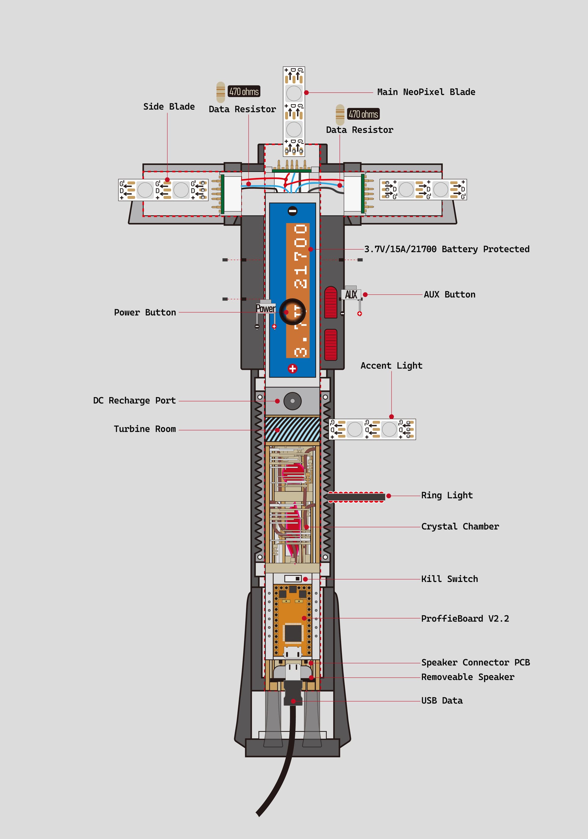
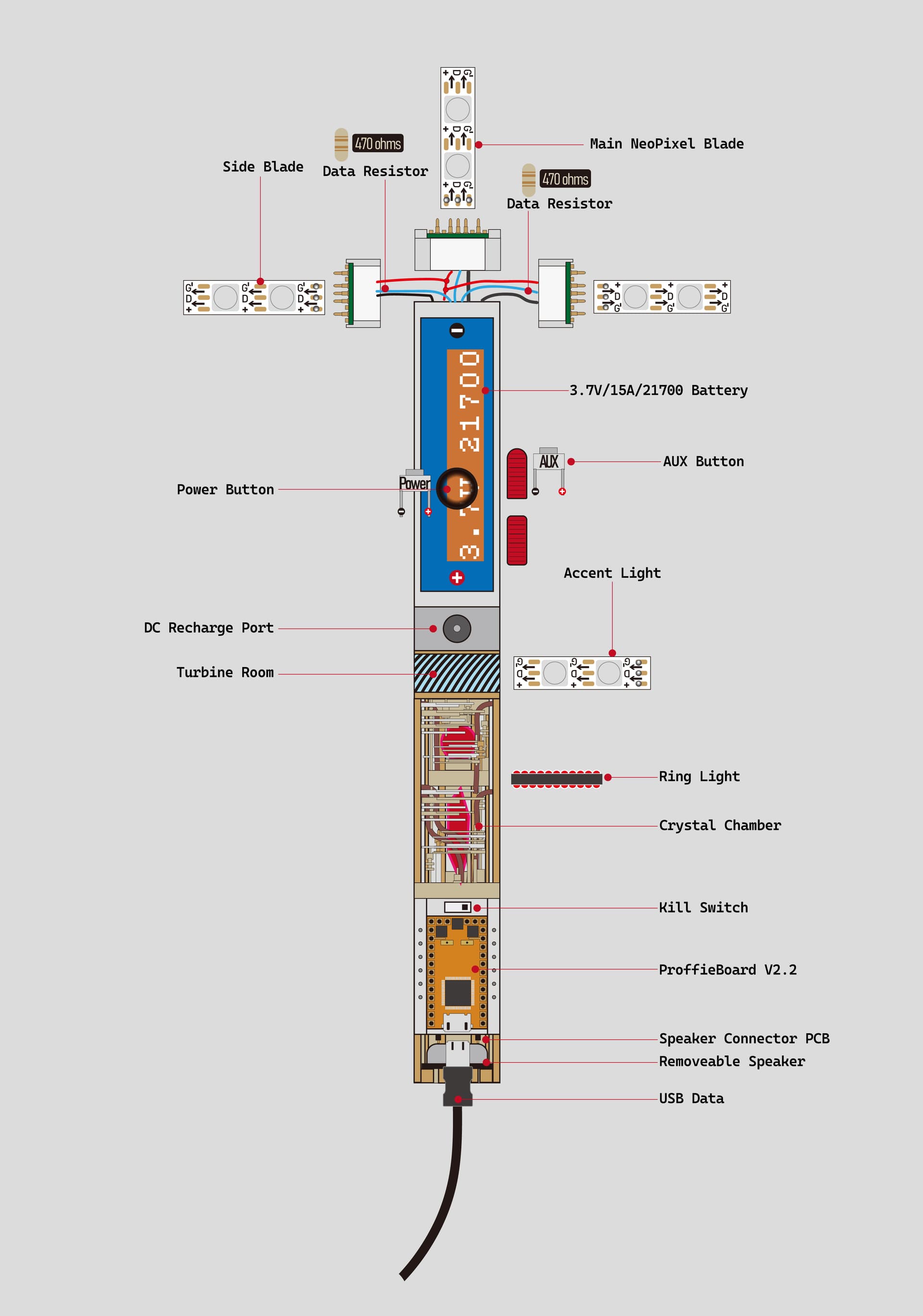
This is a crossguard chassis layout drawing, I want to use a removable speaker so I can access the Proffieboard. All the wires will be hidden in the bottom of the chassis. I want to add two accent lights or one ring light to light up Crystal and Crystal Ball. Can this idea be realized? Any suggestions on building KR Crossguard 2.0 would be appreciated
Everything you want seems possible ![]()
You can run accents as a fourth blade, and getting it to match the blade effects it very easy with Fett263’s library.
Fitting everything in place…not sure until you try.
That’s really true, still trying. I hope I don’t give up…
If combining all accent light as the fourth blade, Does it only need positive connecting in series with the other three blades, Then weld the Data-4 pad and welding negative pad?
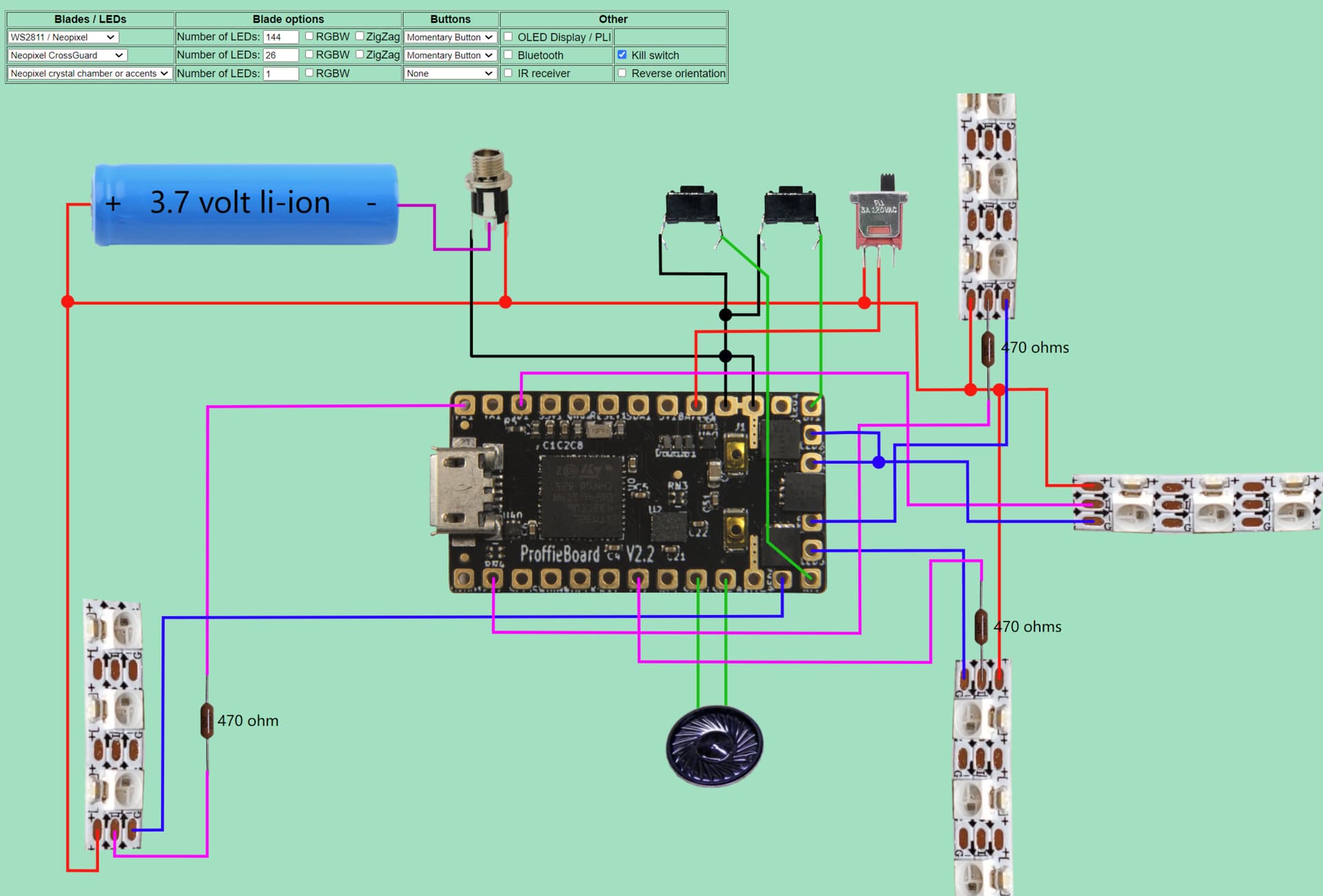
The configurator diagram has your wiring info. The positive line is connected in parallel from the battery to the start of blade 4. Yes to the data and (-) wiring. They go from the indicated LED pads the the ones in the diagram. Don’t forget your resistors ![]()
Thank you for the suggestion, ![]() I got it. All neo pixel(+) goes to the battery (+) in parallel, add 470ohm resistor for data-4, and All neo pixel(-) goes to the LED pads.
I got it. All neo pixel(+) goes to the battery (+) in parallel, add 470ohm resistor for data-4, and All neo pixel(-) goes to the LED pads.