I’m about to wire my first killswitch, and in looking at the configurator wanted to clarify on the wire connections–does the middle pole of the killswitch wire directly and only to the proffieboard, or does it junction in with the rest of the positive wiring? My understanding of the diagram is the circle represent the junctions, so the graphic from the configurator just has the wires overlapping.
The kill switch needs to go in between the battery and the rest of the circuit. It doesn’t matter where the circuit is broken, but it has to be broken somewhere (assuming everything is in series. If you split it up to make parallel runs, you should put the kill switch before that point). The middle pin of the switch gets connected to either the left or right pin depending on the respective switch position.
Think of the kill switch as bit of wire you splice into the circuit which you can easily remove.
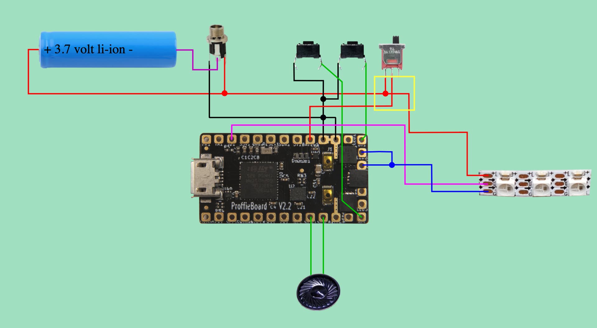
Prof–just the basic 2.2 configurator. Here’s a screenshot with the part I’m clarifying on boxed in yellow.
My understanding is that the middle pole wire goes to the Proffie and the rest are one long chain up through to the blade so that when the switch is “off” there’s no connection between middle and “on” pole (such as ryryog25’s elaborated on above).
Something I’ve meant to ask since my background in higher voltage has always been unless a relay is involved to always have the disconnect on the negative and the positive is the fusible relay:
Why does the switch have to be on the positive line for option 1 if going from power to the board?
BATT- goes to the FETs and the rest of the board
BATT+ does not go to the FETs, just the rest of the board
So cutting BATT- means you’re cutting the full power to the board.
Cutting BATT+ on the other hand leaves the high-power path through the FETs untouched, which is fine since the FETs will cut that path when the CPU is not powered.
Curiosity question–so could I also wire a kill switch along the negative path from the battery without issue, then?
Current saber project doesn’t have a lot of room in the chassis, so the best spot for the kill switch is going to be down near the negative terminal. I’d have fewer wires running to/from the switch if I could use the negative wire.
To add to this, I’ve done a bit of testing. The kill switches we’re all commonly using now can handle up to 11a before getting warm. For this reason most people will say you cannot use a kill switch for the whole saber. I certainly understand that, but in reality it takes a lot to draw 11a. A quad star (four 3535 strips) will approach that on full white, but that’s about it. So realistically, I’d say it’s fine to run everything through so long as you’re moderately thoughtful about it. I recommend using dual fets, dual negative wires, and using the kill switch on the proffie positive circuit only if you’re planning on more than a three strip blade. But I like to overbuild.