Some of you may remember a few years ago I developed the Saber Shield to function as a solid-state kill switch. While it worked great and I’ve installed it in five hilts since, it required a separate momentary switch to be added to the hilt.
I hate having a kill key, and a slide switch that can only be accessed by removing the chassis/unscrewing the hilt is a pain. (my personal feelings)
I started to think about the fact that the Proffie kills power to the blade via the on-board FETs, so the only thing drawing power is the Proffie itself (however small that current may be). So, a kill switch really only needs to cut the Batt+ connection to the board to eliminate parasitic draw…@proffezorn maybe you can confirm this?
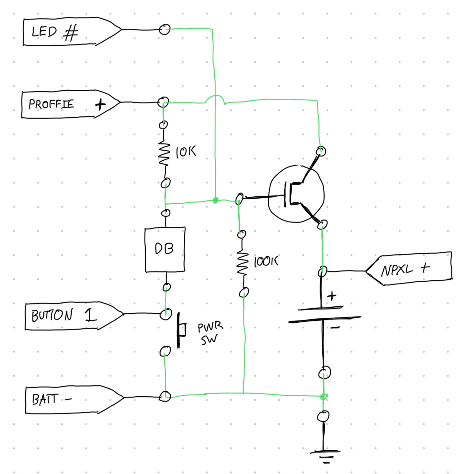
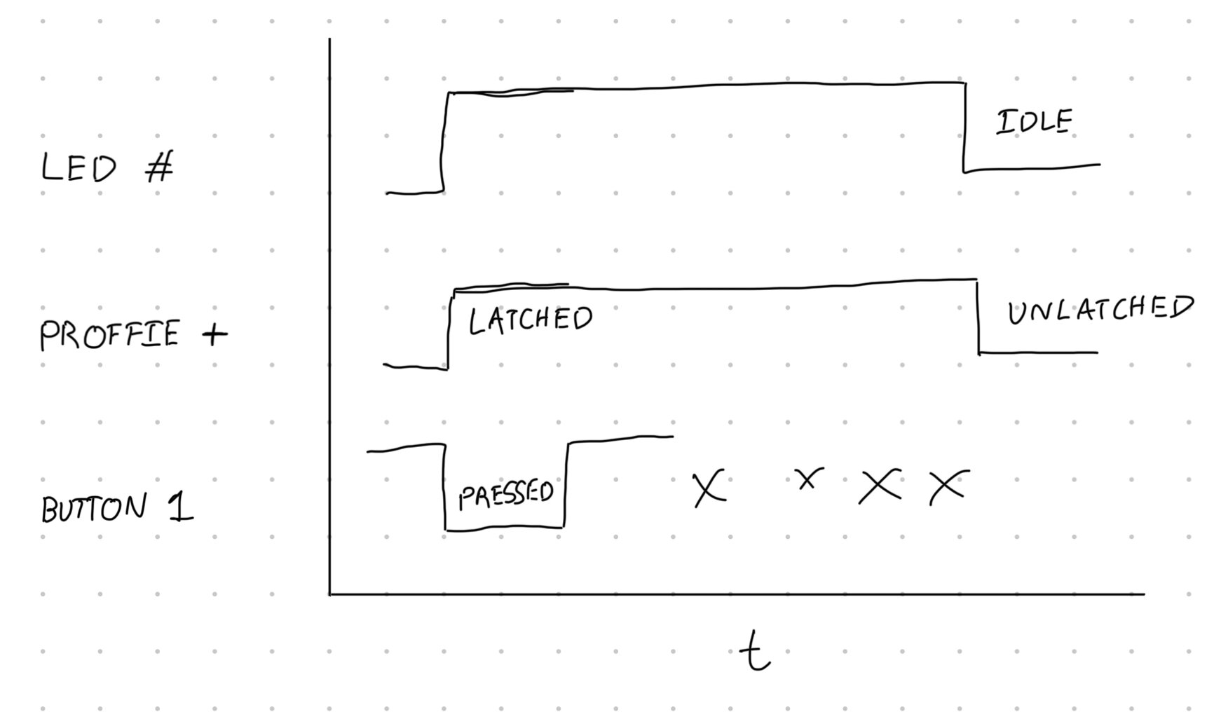
To that end, could we use the power button to trigger a solid state switch that latches itself on? Once latched, further button presses have no effect. To shut down the solid-state switch, we pull the gate of the FET low using on of the LED FETs on the Proffieboard…right before going to idle state, for instance. Long story short, the power button doubles as a kill switch. I’ve drafted up a simple circuit diagram:
This is just a chicken scratch diagram…the FET may have to be a P-channel device, and the values and exact connections might have to change. The “DB” device in the diagram is a MAX6816EUS+T switch debouncer chip. The output goes high for a clean 50ms pulse when the input is pulled low by a switch…perfect for triggering a FET latch.
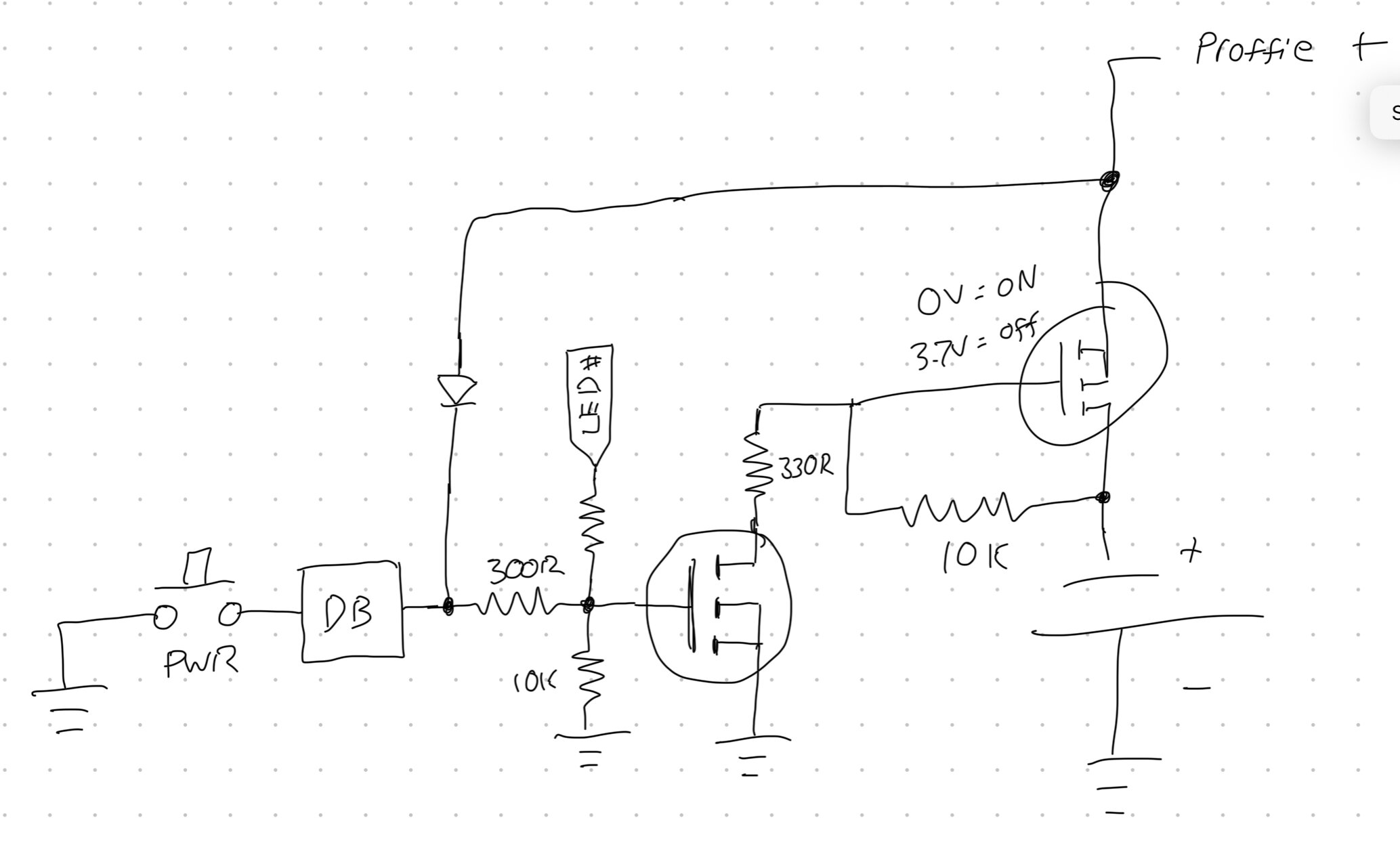
The idea is good, not sure about the circuit. As you say, a pFET might be needed, and that means the pullup/down stuff needs to be inverted. Also, I would probably just use a capacitor instead of a debouncer.
You need the debouncer in this instance to invert the switch signal so it works with the N-channel FET. You could tie the power switch to the gate of the P-channel FET, but then the N-channel FET would pull the Button 1 pin low permanently. The debouncer nicely decouples the button from anything else.
The board will need to pull LED6 low as soon as it wakes up, or it will die.
The capacitor is meant to give the board a little time, but is probably not actually required.
The diode prevents LED6 from pulling the BTN1 input low, so that the button will keep working.
You may also need some code that ignores the power button until it’s been released the first time.
EDIT: It might need a little tweaking, because the pullup in BTN1 might have enough pull to activate the pFET. If this is a problem, it can be fixed by adding another resistor, either on the BTN1 line to make the pullup weaker, or by connecting BTN1 to BATT+ with a resistor to make it pull BTN1 all the way up to BATT+. At that point the circuit should work as expected.
Nice work! I like that a minimal amount of components are needed.
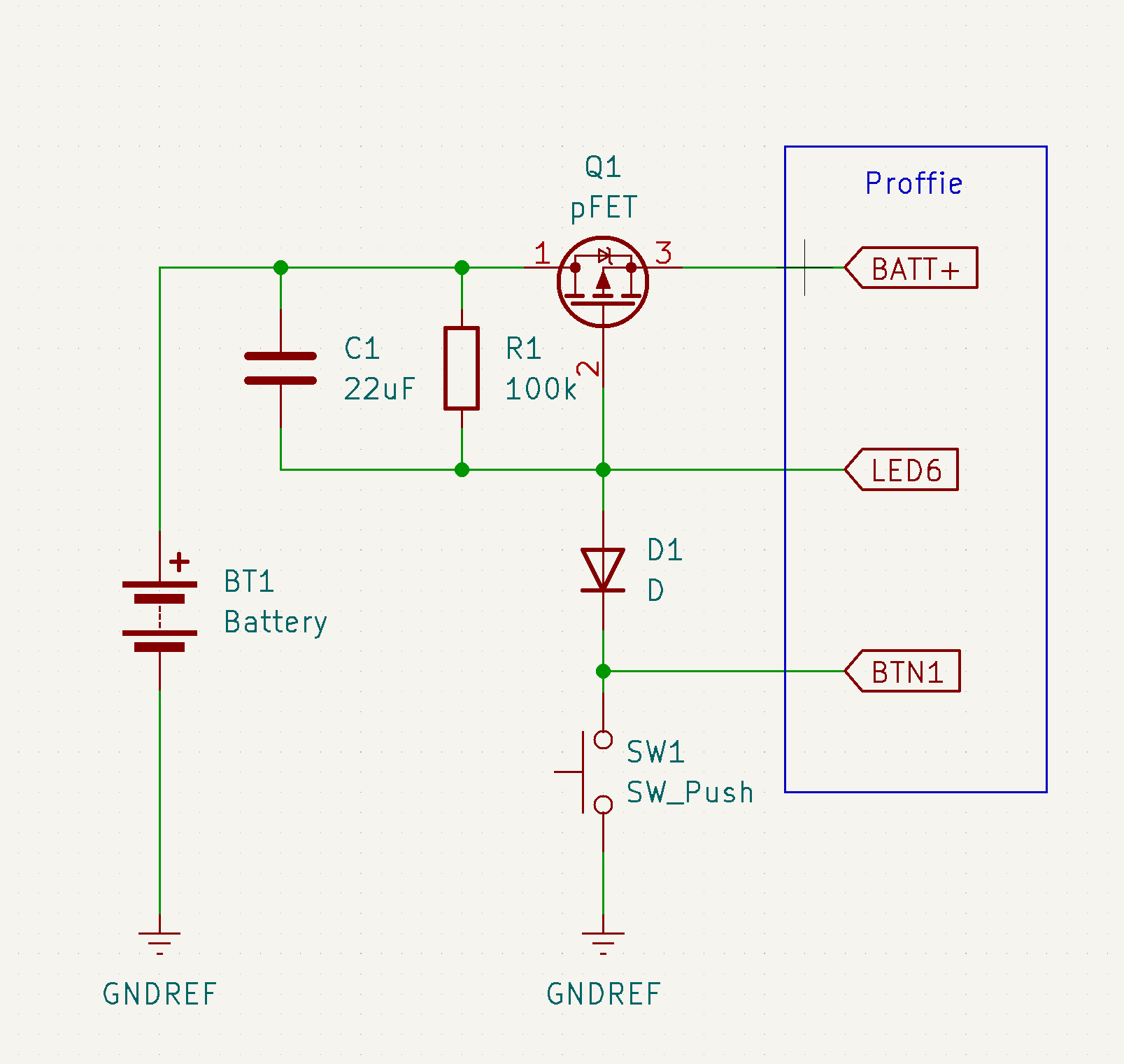
I think you might have pins 1 & 2 mixed up on the P-FET because the way it’s connected now the body diode will connect the Proffie to the battery.
The pull-up on BTN1 shouldn’t be an issue because the FET is off when the Gate is “high” (Vgs = 0V), and R1 should keep the Gate high even if BTN1 is indeterminate.
BTN1 isn’t floating though, it’s pulled to 3.3v with a ~43k resistor.
The problem is of course that 3.3v is usually less than battery voltage, so it might pull down LED6 enough to activate the fet, which would mean that the circuit never turns off…
I guess this only matters when you actually want to cut the power, so you could turn off the pullup for BTN1 before deactivating LED6.
Here are the logic gate P/N’s:
|NC7SZ14L6X|IC INVERTER 1CH 1-INP 6MICROPAK|1uA
|NC7SZ32L6X|IC GATE OR 1CH 2-INP 6MICROPAK|2uA
|NC7SZ00L6X|IC GATE NAND 1CH 2-INP 6MICROPAK|2uA
I considered an Attiny45 or 85, but then you add the extra complication of programming it, which makes it harder for others to build. You could implement the above circuit with discrete components (transistors/diodes/ect), but then your part count goes way up and so does the assembly work.
The logic chips are cheap, robust, and have low quiescent current draw.
I have a few issues I’d like to resolve.
The Batt+ pad is located under the Proffieboard 5V pad, which could be an issue depending on clearances during soldering.
Also, the overall board is a bit bigger than I wanted…so I’m going back to the drawing board on component selection/layout.
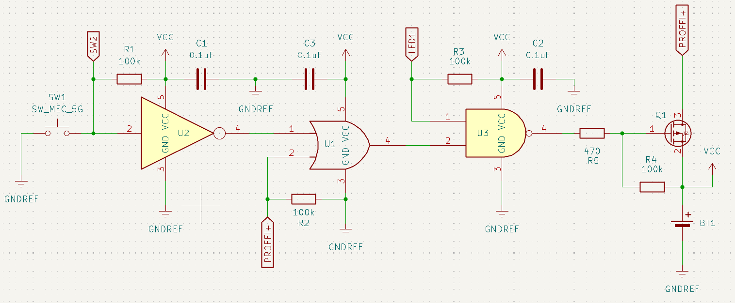
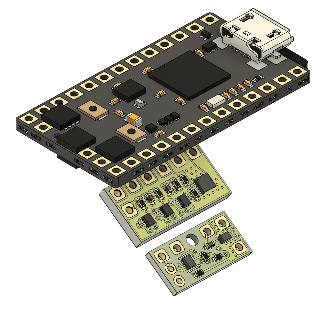
I went back to the drawing board on the circuit design and managed to greatly simplify the logic using a configurable gate chip (SN74LVC1G97DRYR) and a high side switching IC (TPS22995RZFR) instead of a P-channel mosfet.
The board is now only 6.1 mm x 12.7 mm x 1 mm and should fit in any hilt. It fits comfortably in a 1-inch ID hilt between the Proffie and an 18650.
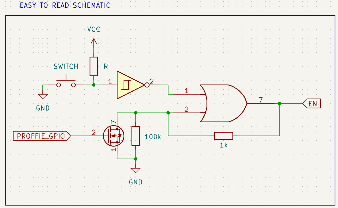
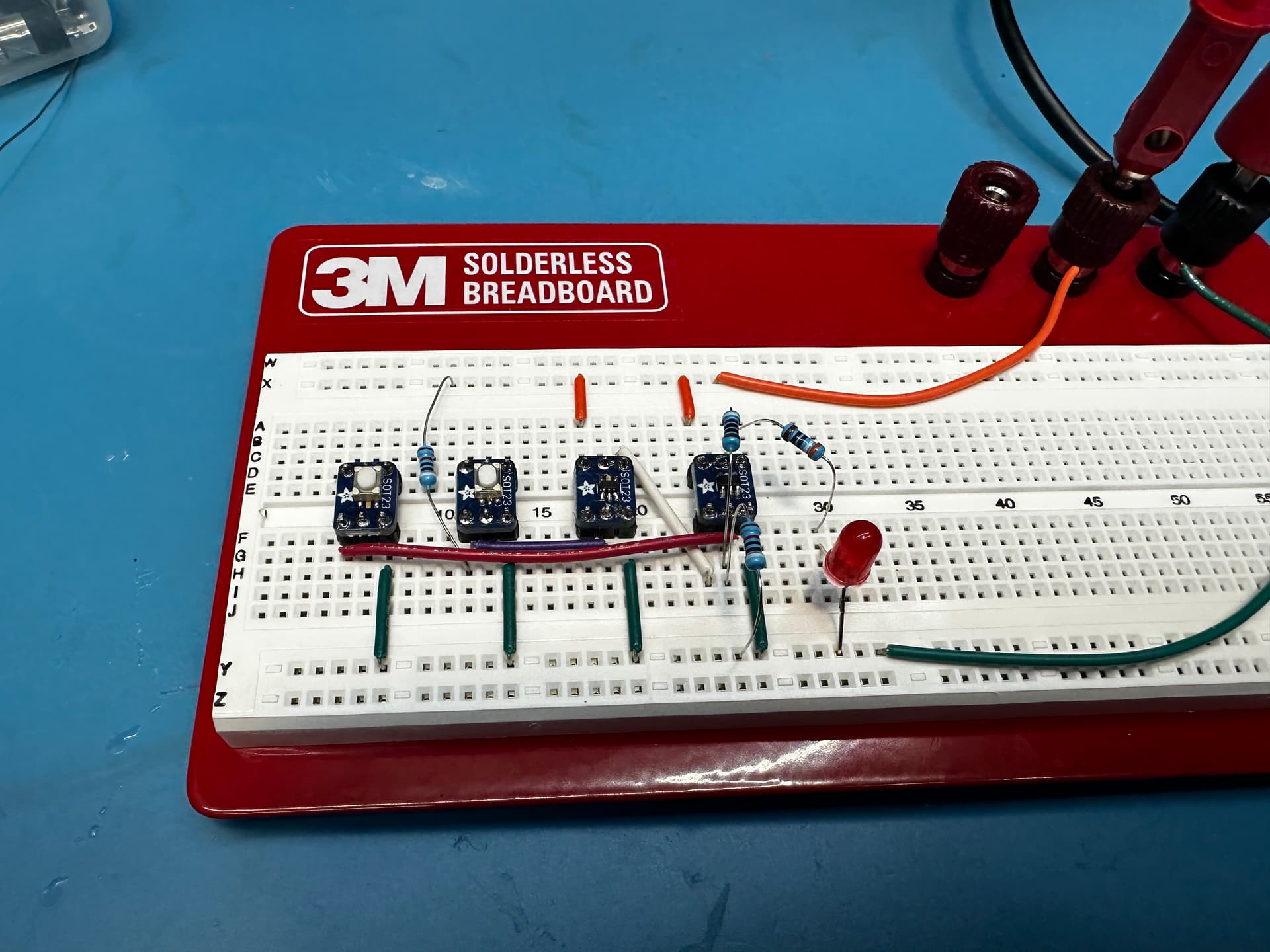
The function works perfectly. A button press latches on the OR gate, and only shorting the other OR input to ground causes the circuit to turn off…any button presses after the circuit turns on have no effect. The button pin is not affected by the latch state, which means it still works as a button for the Proffieboard. A 1K resistor prevents the OR gate from burning out when the FET is shorted to ground, but also allows the output of the gate to pull the input high through the 1:10 divider. The 100k resistor to ground ensures the input of the gate doesn’t float when power is off (the OR gate output goes high-Z). Here is a short video of the circuit working…the Proffieboard FET is replaced with a simple button in this example:
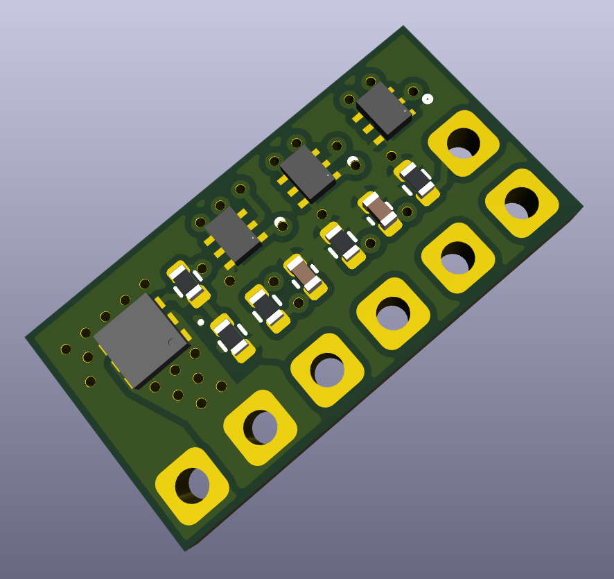
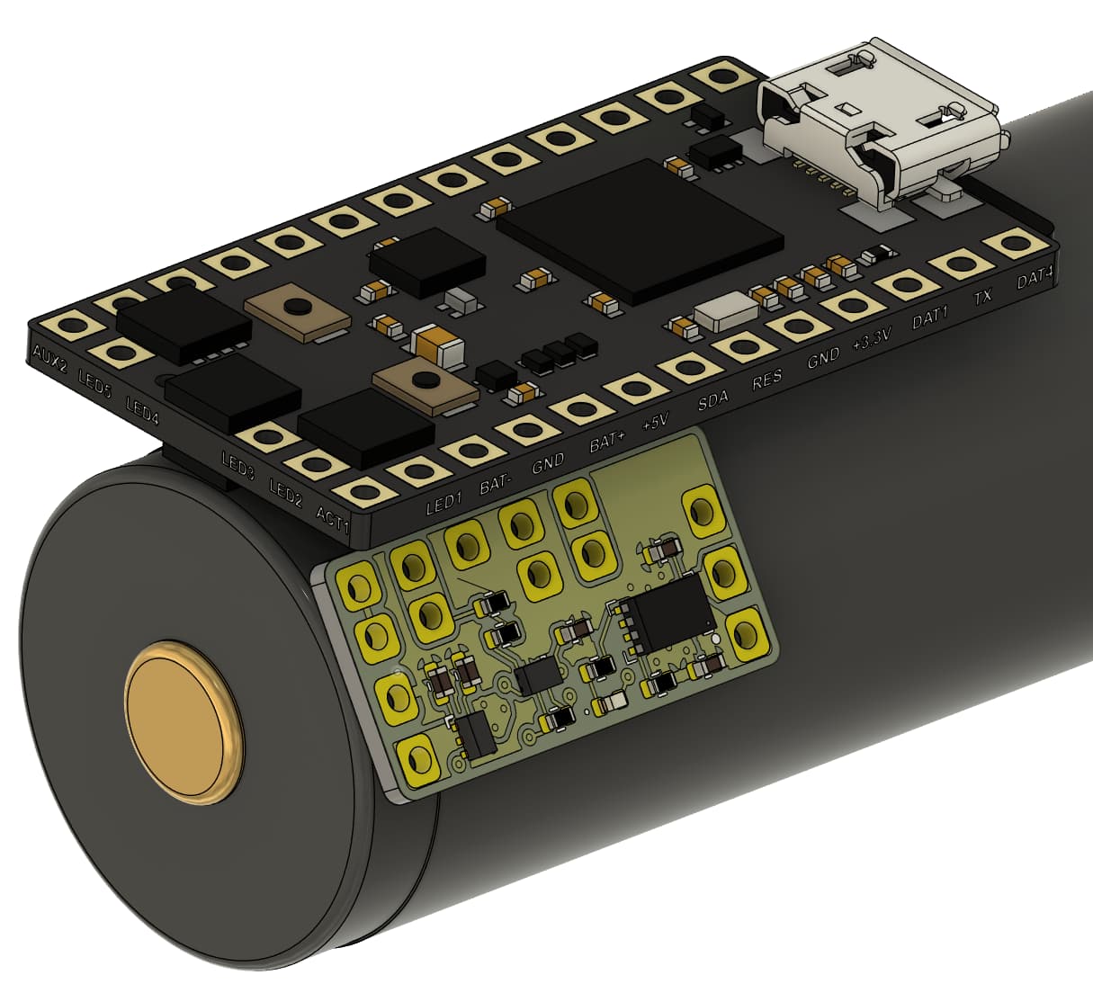
Okay, this project got shelved for a bunch of other stuff, but I finally started back and finished the PCB design.
This version has a battery charger integrated, as well as a high current ground connection.
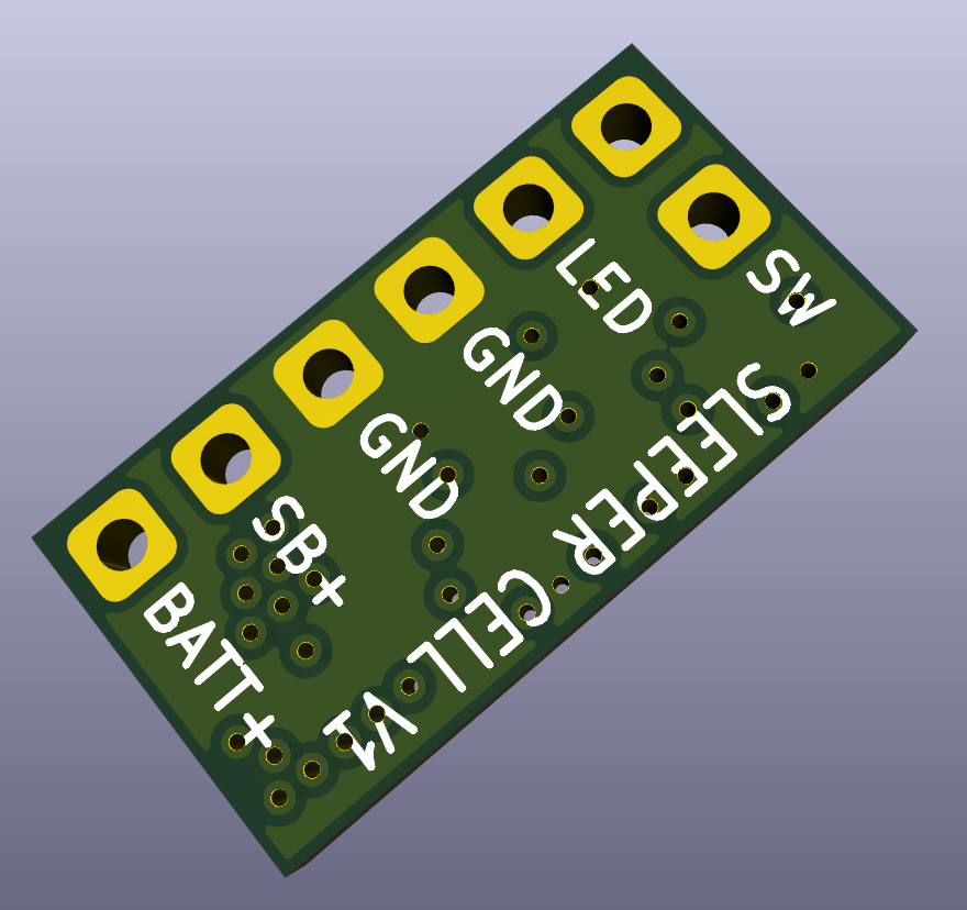
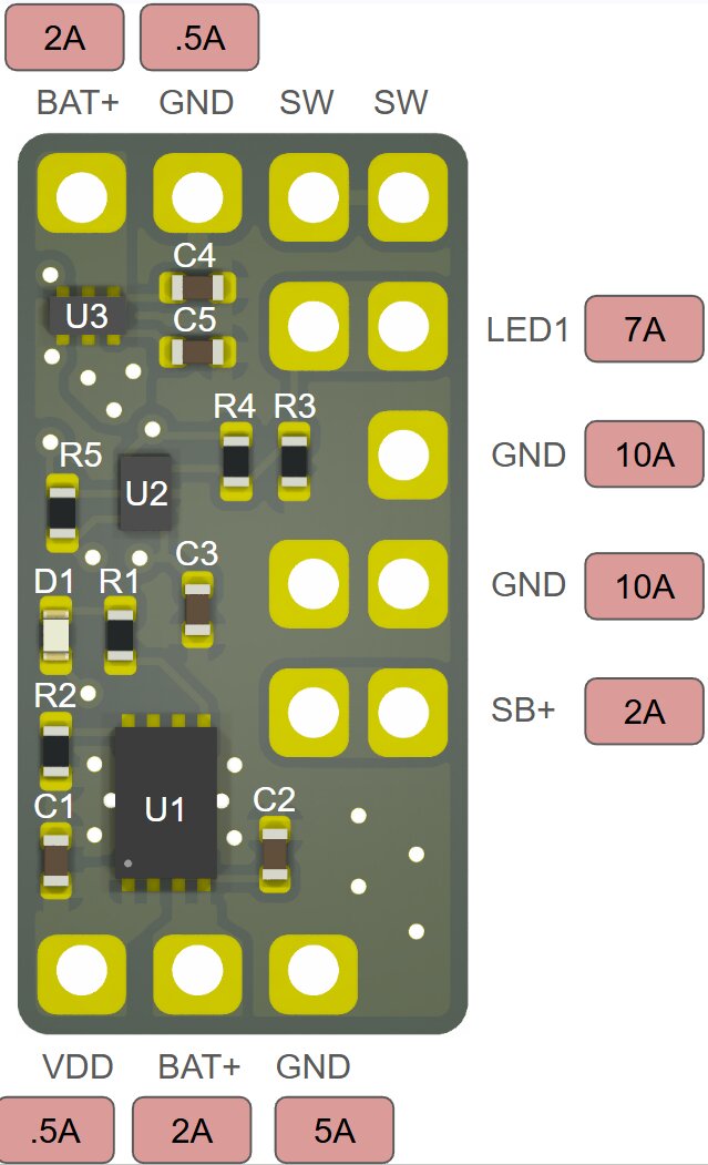
Here is a connection diagram with the rated pin currents:
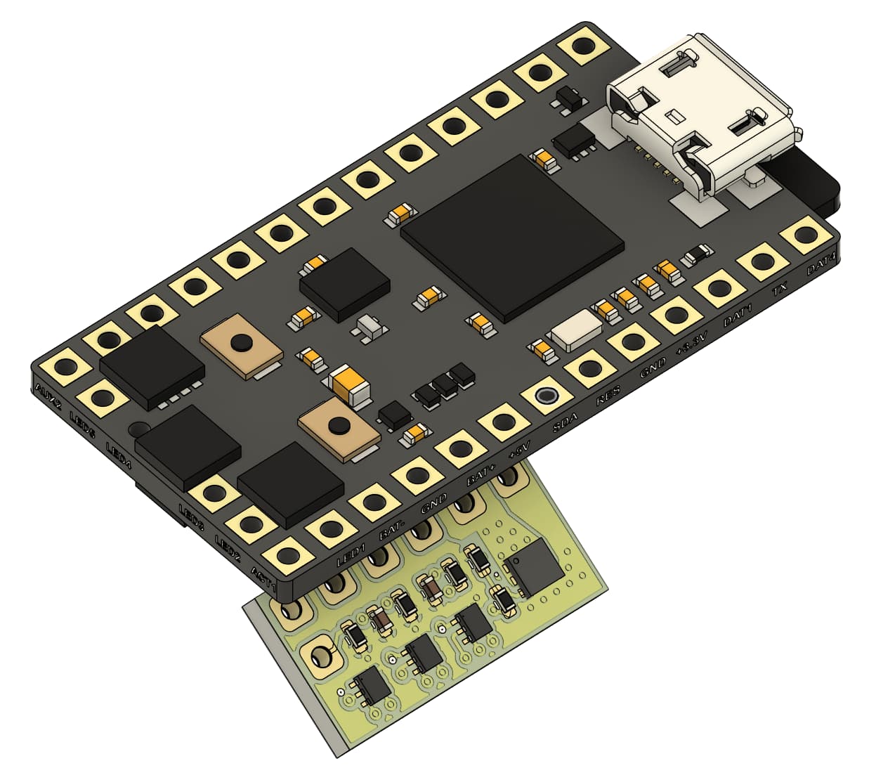
The board is pin-compatible with the Proffieboard V2.2 and V3.9, and allows the battery to be connected to this board instead of the Proffieboard (Except the blade positive). It will fit in a 25mm ID hilt next to an 18650 and Proffieboard:
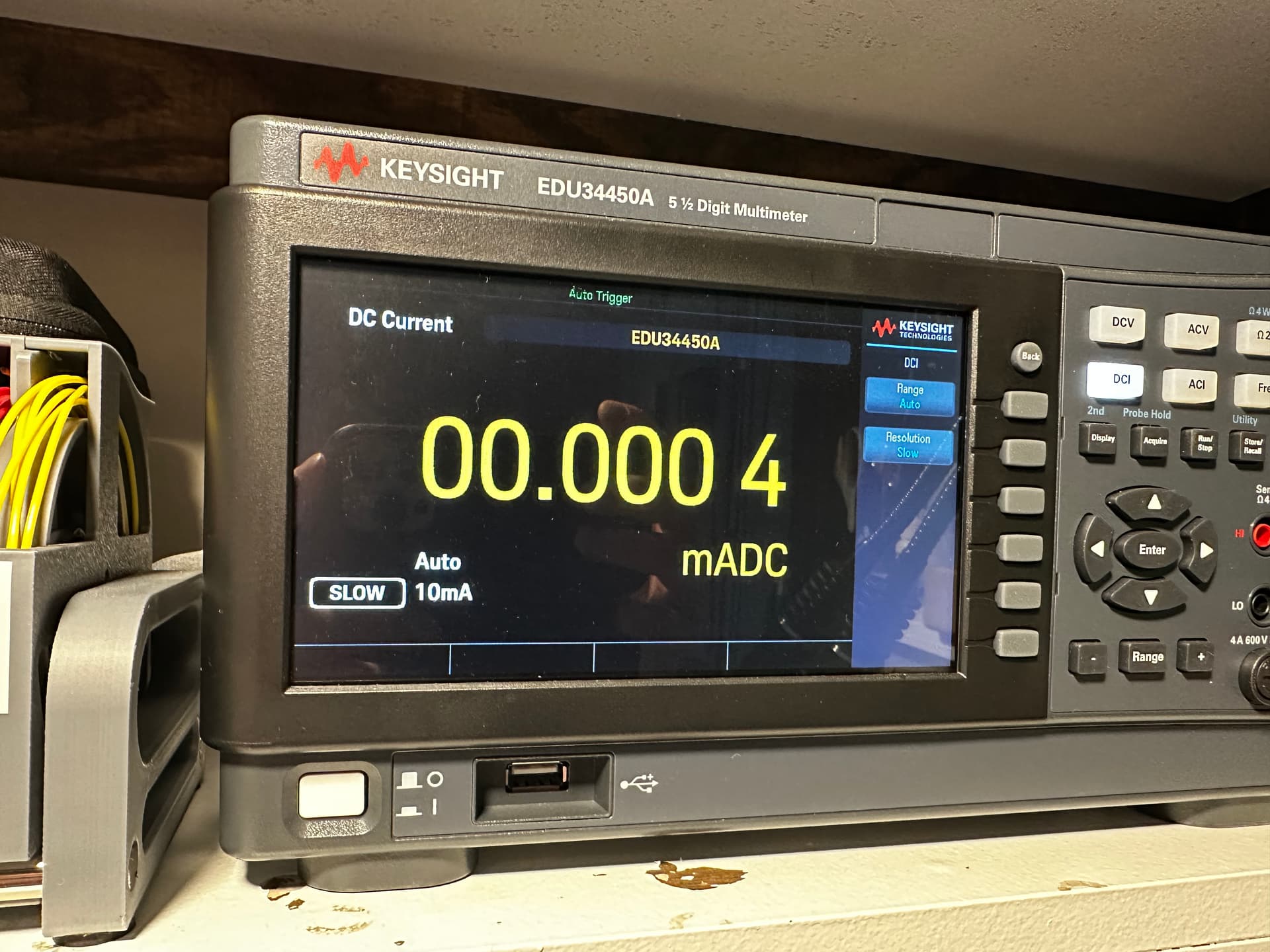
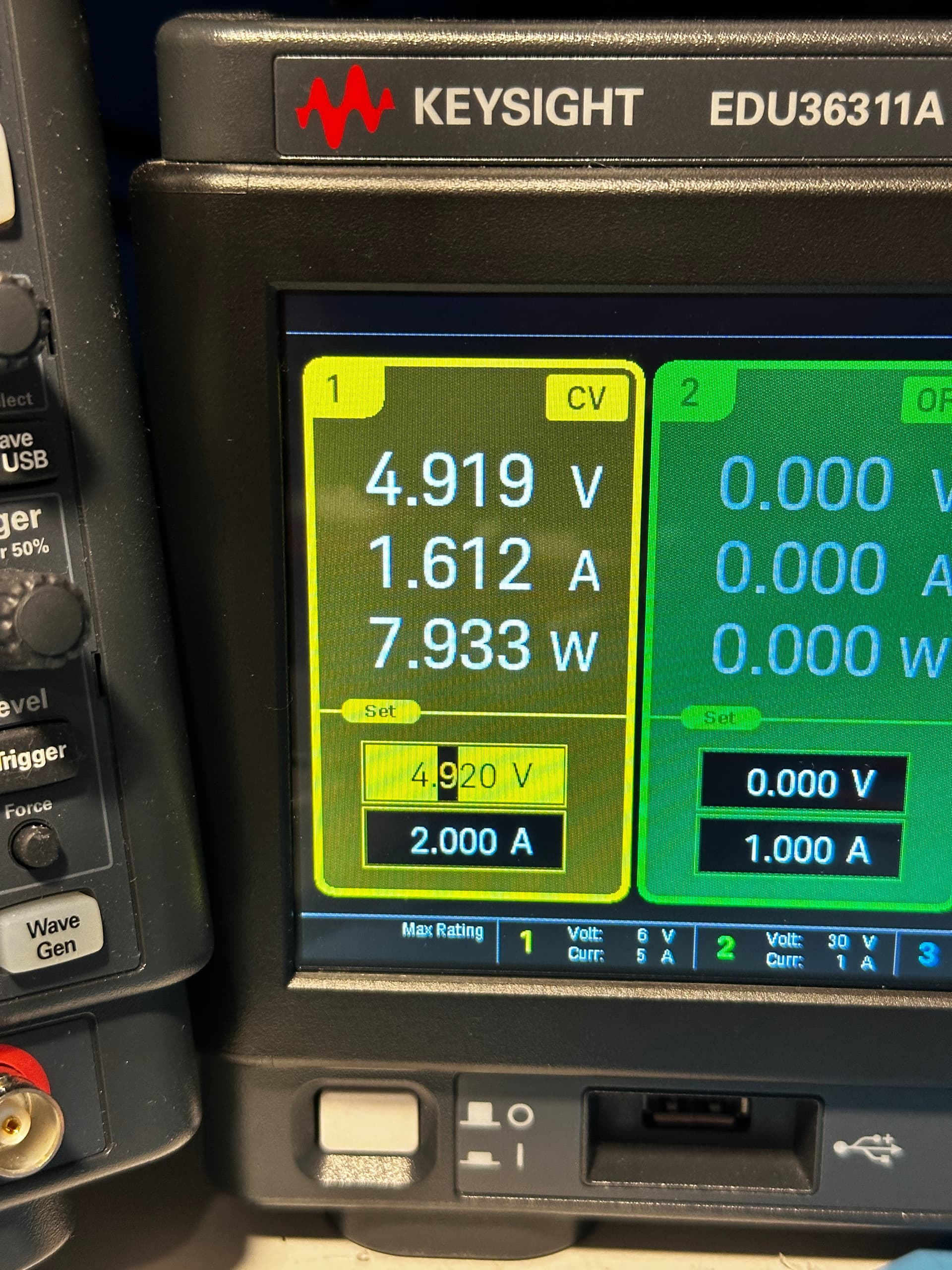
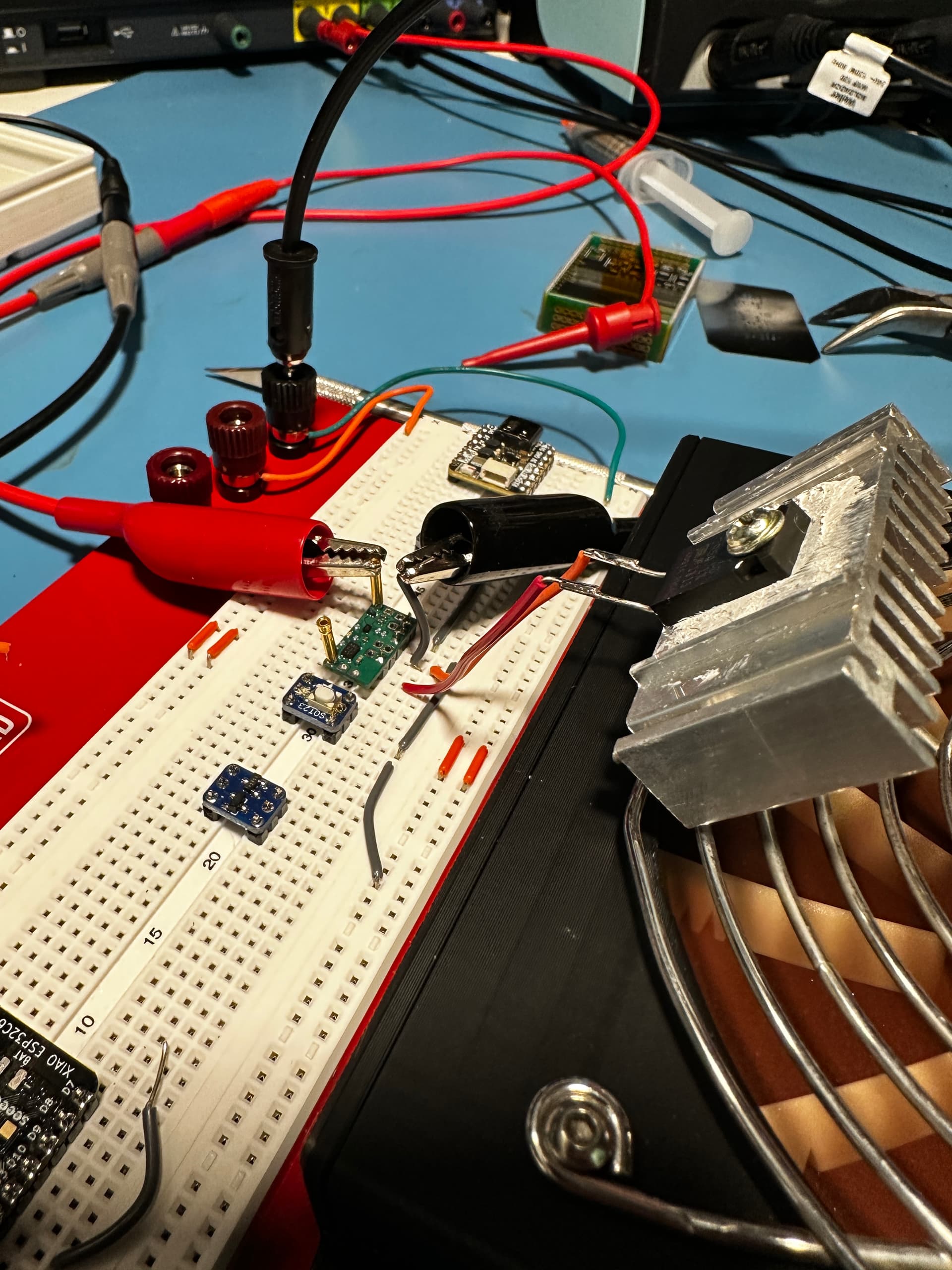
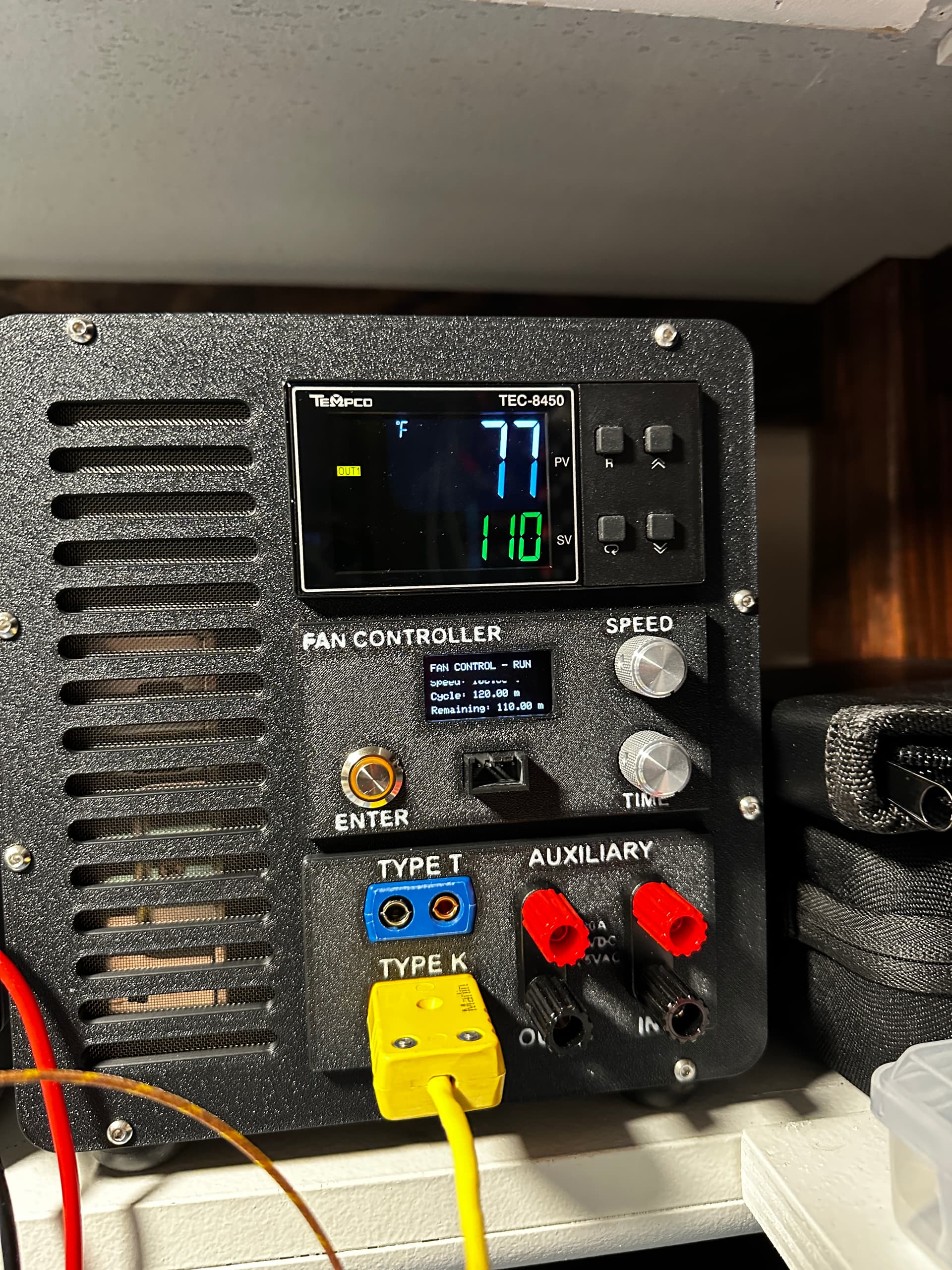
So far I have bench tested the logic (working), and just finished stress testing the high-side switch IC. With a 3-ohm load running at 4.9V and 1.6A (7.4W), the chip package is sitting at 77F after an hour…just above ambient of 74F: