Issue trying to use NeoPixel Stick

Hi there, this is my first time posting in this forum. I’m hoping to get some help with an issue im facing.
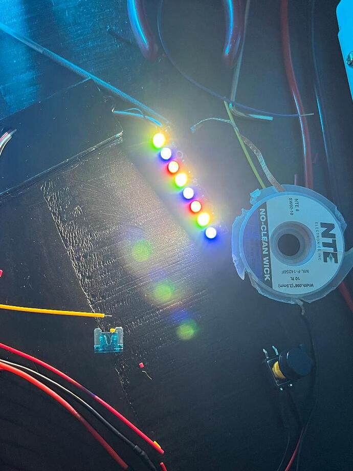
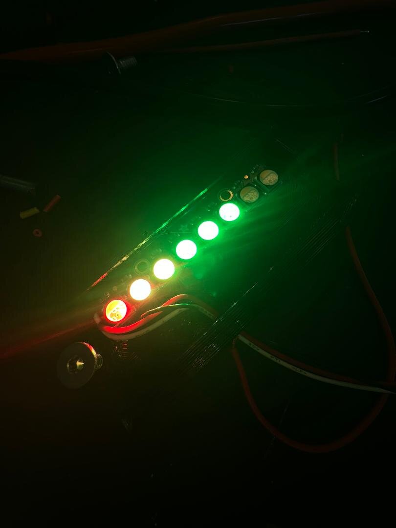
I have a proffieboard v3.9 and I’m trying to hook up a NeoPixel Stick. The actually stick im using can be found here. I made sure the stick worked with my code by testing it out on an arduino uno. The stick works fine and lights up green, however when trying to use the stick on the proffieboard, the entire stick lights up with green, blue, red and repeats on the entire stick. I have the 5v pin of the the proffieboard going to the stick and the gnd going to the proffieboard gnd. The data pin i’ve tried many different pads like free 3, data 3 and even the LED 4 and 5 pads. My hope is to use the stick as a battery level indicator. I added the following code to the ProffieOS.ino file.

#include <Adafruit_NeoPixel.h>
Adafruit_NeoPixel strip(8, NEOPIXEL_BATTERY_LEVEL_PIN, NEO_GRBW + NEO_KHZ800);

setup() {
strip.begin();

//reset of the setup code
}

loop() {
  if (SaberBase::IsOn()) {
      strip.clear();
      for(int i=0; i<8; i++) { // For each pixel...
  
        // Here we're using a moderately bright green color:
        strip.setPixelColor(i, strip.Color(0, 150, 0));
    
        strip.show();   // Send the updated pixel colors to the hardware.
       }
   }

  //rest of the loop code
}

This is how the stick lights up with that code on the proffieboard.

I’m not sure what the issue is, is there a better way to achieve what i’m doing? Has anyone used this library with their proffieboard?

Thanks.

Try NEO_GRB instead and see if it works better.

Note that you won’t need the adafruit library to use this as a PLI if you’re planning to use ProffieOS. ProffieOS can already do all that.

Thanks for the response. I’ve tried all the combos like NEO_GRBW but nothing seemed to work. One thing I’m confused on, the mapping chart shows both pin 4 and 5 are assigned to the data 3 pad. The data 3 pad is the one I’m currently using for the data pin of the stick. I tried setting NEOPIXEL_BATTERY_LEVEL_PIN to 4 and also 5. The stick doesn’t light up at all using either of those pins. Is there different code i can use? Or what pad and pin config do you recommend?

How would i control this stick without using the adafruit library?

I don’t really know if the Adafruit library supports proffieboards at all to be honest.

ProffieOS can control an arbitrary number of “blades”. Any kind of array of lights is considered a blade, not just the main lightsaber blade. Crystal chambers, accent lights and PLIs are all considered blades.

To add another blade, you need to do three things:

  1. Increase NUM_BLADES in your config file by one.
  2. Add another blade defintion to your blades[] array.
  3. Add another style to each preset.

You can use the the configurator to see examples of this, even if none of them are explicitly for a PLI stick.

The styles determine what the blade actually shows.
The configurator uses very plain and generic styles for all blades, but if you want a battery level indicator, you could use something like this:

   StylePtr<InOutHelperX<Gradient<Red,Orange,Yellow,Green,Green,Green,Green>, BatteryLevel>>()

Thank you, i’ll give that a try!

When i try to update the Presets, i get the following error

 error: cannot convert 'Preset*' to 'BladeBase*' in initialization
  115 |     CONFIGARRAY(presets) }
      |                 ^~~~~~~
      |                 |
      |                 Preset*

Heres what i have for the Presets and the bladeConfig

Preset presets[] = {
  { "Luke;MC", "tracks/Luke.wav",
    StylePtr<InOutHelper<OnSpark<Blast<LocalizedClash<Lockup<AudioFlicker<Green,Rgb16<0,38402,0>>,Pulsing<Gradient<AudioFlicker<Green,Rgb16<0,38402,0>>,AudioFlicker<Green,Rgb16<0,38402,0>>,HumpFlicker<OrangeRed,Pink,50>,AudioFlicker<Green,Rgb16<0,38402,0>>,AudioFlicker<Green,Rgb16<0,38402,0>>>,Gradient<AudioFlicker<Green,Rgb16<0,38402,0>>,AudioFlicker<Green,Rgb16<0,38402,0>>,HumpFlicker<OrangeRed,Pink,50>,AudioFlicker<Green,Rgb16<0,38402,0>>,AudioFlicker<Green,Rgb16<0,38402,0>>,AudioFlicker<Green,Rgb16<0,38402,0>>>,3500>,Gradient<AudioFlicker<Cyan,DeepSkyBlue>,AudioFlicker<Cyan,DeepSkyBlue>,HumpFlicker<Pink,OrangeRed,50>>>,Pink>,Pink>,Pink,400>,200,500>>()
  },
  { "BatteryLevel", "tracks/none.wav", 
    StylePtr<InOutHelperX<Gradient<Red,Orange,Yellow,Green,Green,Green,Green>, BatteryLevel>>()
  }
};

BladeConfig blades[] = {
  { 0, WS281XBladePtr<128, bladePin, Color8::GRB, PowerPINS<bladePowerPin2, bladePowerPin3> >(),
    CONFIGARRAY(presets) }
};

Im very new to proffieboards so im not sure if im doing this right or not. Also, what pin should i use for the data line of the LED stick? Would the data line be bladePowerPin2 Im powering the stick using the onboard 5v pad.

Here is my entire custom config file

#ifdef CONFIG_TOP
#include "proffieboard_v3_config.h"
#define NUM_BLADES 2
#define NUM_BUTTONS 1
#define VOLUME 1400
const unsigned int maxLedsPerStrip = 128;
#define CLASH_THRESHOLD_G 1.8
#define ENABLE_AUDIO
#define ENABLE_MOTION
#define ENABLE_WS2811
#define ENABLE_SD
#define ENABLE_SERIAL

#define DISABLE_DIAGNOSTIC_COMMANDS
#define ORIENTATION ORIENTATION_USB_TOWARDS_BLADE
#define FETT263_MULTI_PHASE

#define FETT263_TWIST_ON_NO_BM 
#define FETT263_TWIST_ON 
#define FETT263_TWIST_OFF    

#define FETT263_STAB_ON_NO_BM                                              
#define FETT263_STAB_ON                                

#define FETT263_SWING_ON_SPEED 500
#define FETT263_SWING_ON_NO_BM
#define FETT263_SWING_ON
#define FETT263_SWING_OFF

#define MOTION_TIMEOUT 60 * 3 * 1000  

#define FETT263_THRUST_ON
#define FETT263_THRUST_OFF
#define FETT263_DISABLE_COPY_PRESET 

#define ENABLE_SSD1306
// Max 20 characters
#define BLE_PASSWORD "your password"
// Max 32 characters.
#define BLE_NAME "Your Saber Name"
// Max 9 characters
#define BLE_SHORTNAME "Saber"

#define MOTION_TIMEOUT 60 * 3 * 800               
#endif

#ifdef CONFIG_PROP
#include "../props/saber_fett263_buttons.h"

#endif

#ifdef CONFIG_PRESETS


// Fire speed, valid values are 1 - 10
#define FIRE1_SPEED 2
// How long to wait before firing up crossguards.
#define FIRE1_DELAY 800

// Each of these have three values: A, B, C
// A = non-random intensity
// B = random intensity
// C = cooling
// The first two control temperature, and as we add
// A + rnd(B) to the base of the blade each animation frame.
// The second controls how rapidly the fire cools down

// This is used during normal operation.
#define FIRE1_NORMAL 0, 1000, 2

// This is used when a clash occurs
#define FIRE1_CLASH  3000, 0, 0

// This is used during lockup.
#define FIRE1_LOCKUP 0, 5000, 10

// Helper
#define FIRE1PTR(NUM, DELAY) \
  StyleFirePtr<RED, YELLOW, NUM, DELAY, FIRE1_SPEED, \
    FIRE1_NORMAL, FIRE1_CLASH, FIRE1_LOCKUP>()

//#define bladePowerPin1 4

#define MOSFET_CONTROL_PIN 8  // Define the MOSFET pin

#define NEOPIXEL_BATTERY_LEVEL_PIN 5

#define HALL_SENSOR_PIN 7  // Pin 7 for Hall effect sensor
#define MOTOR_PWM_PIN 8    // Pin for motor PWM control
#define MOTOR_DIR_PIN 9    // Pin for motor direction
#define ROTATIONS_COUNT 20

Preset presets[] = {
  { "Luke;MC", "tracks/Luke.wav",
    StylePtr<InOutHelper<OnSpark<Blast<LocalizedClash<Lockup<AudioFlicker<Green,Rgb16<0,38402,0>>,Pulsing<Gradient<AudioFlicker<Green,Rgb16<0,38402,0>>,AudioFlicker<Green,Rgb16<0,38402,0>>,HumpFlicker<OrangeRed,Pink,50>,AudioFlicker<Green,Rgb16<0,38402,0>>,AudioFlicker<Green,Rgb16<0,38402,0>>>,Gradient<AudioFlicker<Green,Rgb16<0,38402,0>>,AudioFlicker<Green,Rgb16<0,38402,0>>,HumpFlicker<OrangeRed,Pink,50>,AudioFlicker<Green,Rgb16<0,38402,0>>,AudioFlicker<Green,Rgb16<0,38402,0>>,AudioFlicker<Green,Rgb16<0,38402,0>>>,3500>,Gradient<AudioFlicker<Cyan,DeepSkyBlue>,AudioFlicker<Cyan,DeepSkyBlue>,HumpFlicker<Pink,OrangeRed,50>>>,Pink>,Pink>,Pink,400>,200,500>>()
  },
  { "BatteryLevel", "tracks/none.wav", 
    StylePtr<InOutHelperX<Gradient<Red,Orange,Yellow,Green,Green,Green,Green>, BatteryLevel>>()
  }
};

BladeConfig blades[] = {
  { 0, WS281XBladePtr<128, bladePin, Color8::GRB, PowerPINS<bladePowerPin2, bladePowerPin3> >(),
    CONFIGARRAY(presets) }
};

#include "../props/prop_base.h" 

#endif

#ifdef CONFIG_BUTTONS
Button PowerButton(BUTTON_POWER, powerButtonPin, "pow");
Button AuxButton(BUTTON_AUX, auxPin, "aux");
#endif
You have NUM_BLADES set to two, but only one WS281XBladePtr blade in your blades array.

No, a bladePowerPin# is a (at least 1-6) MOSFET controlled GND. A controlled power pin.

You would want a blade#Pin for data. (e.g. blade2Pin)

I would strongly advise against this. The 5V is used by onboard components and isn’t really meant to drive neopixels. If you’re thinking you need the 5V because the neopixels are 5V, they’ll run just fine off the battery’s nominal 3.7V. For power control you’d wire GND to one of the aforementioned power pins and specify it in the blade’s PowerPINS list.

The blade arrays should look something like:

BladeConfig blades[] = {
  { 0, 
    WS281XBladePtr<128, bladePin, Color8::GRB, PowerPINS<bladePowerPin2, bladePowerPin3> >(),
    WS281XBladePtr<#, blade2Pin, Color8::GRB, PowerPINS<bladePowerPin6> >(),
    CONFIGARRAY(presets) }
};

This is set up for one blade, even though NUM_BLADES is 2.
What you want is something like this:

BladeConfig blades[] = {
  { 0, 
    WS281XBladePtr<128, bladePin, Color8::GRB, PowerPINS<bladePowerPin2, bladePowerPin3> >(),
    WS281XBladePtr<10, blade2Pin, Color8::GRB, PowerPINS<bladePowerPin1> >(),
    CONFIGARRAY(presets) }
};

(This assumes that your pixel strip is hooked up to Data2 and gets negative power from LED1)

This does not belong in your config file, please remove.

What you did here was to create two different presets, with one blade each.
What you actually want is one preset with two blades, like:

  { "Luke;MC", "tracks/Luke.wav",
    StylePtr<InOutHelper<OnSpark<Blast<LocalizedClash<Lockup<AudioFlicker<Green,Rgb16<0,38402,0>>,Pulsing<Gradient<AudioFlicker<Green,Rgb16<0,38402,0>>,AudioFlicker<Green,Rgb16<0,38402,0>>,HumpFlicker<OrangeRed,Pink,50>,AudioFlicker<Green,Rgb16<0,38402,0>>,AudioFlicker<Green,Rgb16<0,38402,0>>>,Gradient<AudioFlicker<Green,Rgb16<0,38402,0>>,AudioFlicker<Green,Rgb16<0,38402,0>>,HumpFlicker<OrangeRed,Pink,50>,AudioFlicker<Green,Rgb16<0,38402,0>>,AudioFlicker<Green,Rgb16<0,38402,0>>,AudioFlicker<Green,Rgb16<0,38402,0>>>,3500>,Gradient<AudioFlicker<Cyan,DeepSkyBlue>,AudioFlicker<Cyan,DeepSkyBlue>,HumpFlicker<Pink,OrangeRed,50>>>,Pink>,Pink>,Pink,400>,200,500>>(),
    StylePtr<InOutHelperX<Gradient<Red,Orange,Yellow,Green,Green,Green,Green>, BatteryLevel>>()
  }
1 Like

Thank you all for the help, i really appreciate it!
So, would the wiring for the LED stick be pos = lipo battery POS, GND = anyone of the LED pads? and the data wire to one of the free pads or data pads? Sorry, it’s a bit confusing to me.

That is exactly right.

1 Like

Well, I never clicked send before, so I guess might as well not waste this responses I wrote:

From the product page:
“this NeoPixel Stick use to come with WS2812B LEDs and now comes with SKC6812 LEDs, these are the same protocol”

So since it’s still just WS281X, you just use it like any typical addressable pixel strip.

Remove that setup code from ProffieOS.ino.
Use battery power, not the 5V pad for (+).
Ground through LED pad 4 (or whichever you choose).
Data on data3 (or whichever you choose).

Set your blade config to (based on above numbers)

WS281XBladePtr<8, blade3Pin, Color8::GRB, PowerPINS<bladePowerPin4> >()
1 Like

Thank all for the great responses. I’ll work on it tomorrow and let you know how it goes! This Proffieboard is awesome!

The code worked like a charm!

Thanks again for the help! One more question.

Im trying to control something using PWM, i’ve assign free 3 as the pin. From the mapping chart, it looks like the free 3 is PWM capable. Is that correct?

That is correct. If you need to drive something that requires power, using the LED* pads might be better than using the Free* pads.

PWM outputs can also be bound to styles through the blades array, same as neopixels, it just depends on what you’re doing.

Im powering a dc motor, so i need to be able to send a pwm signal to the motor controller. Free 3 pad would be ok for this? Im setting it as pin 9 in code. Os this functionality is separate from the blades.

Free 3 should be fine.
I would use a SimpleBlade for this, by default SimplBlade outputs ~800Hz, is the motor controller ok with that?

Motors can also be driven directly from LED1-6 if needed.

Im using this motor driver
I have a step up converter that takes the 3.7v and converts it to 12v. Im grounding the converter and the motor driver to the proffieboard common ground. Can i use one of the LED pins to send the PWM signal to the motor driver? Right now im trying to get it to work using free 3 as the pwm signal and the data 4 pin as the motor direction, but its not working.

Seems like it should work.
Are you getting a PWM signal?
What does your setup/code look like?

Here my code. I’m running the motor in the setup function just to test it out.

#define MOTOR_PWM_PIN 9   // Pin for motor PWM control
#define MOTOR_DIR_PIN 6    // Pin for motor direction

//code in the setup function
pinMode(MOTOR_PWM_PIN, OUTPUT);       // Setup motor control
pinMode(MOTOR_DIR_PIN, OUTPUT);       // Setup motor direction

// Run motor forward for 3 seconds
digitalWrite(MOTOR_DIR_PIN, HIGH);  // Set direction to forward
analogWrite(MOTOR_PWM_PIN, 255);    // Set full speed (255 = max)
delay(3000);  // Run for 3 seconds
  
// Run motor backward for 3 seconds
digitalWrite(MOTOR_DIR_PIN, LOW);  // Set direction to reverse
analogWrite(MOTOR_PWM_PIN, 255);   // Set full speed (255 = max)
delay(3000);  // Run for 3 seconds
  
// Stop the motor
analogWrite(MOTOR_PWM_PIN, 0);     // Set speed to 0 (disable motor)

I just have a multimeter, i dont really have a way to test the pwm signal. Only other choice would be to test the motor driver on an Uno.

I think this should work.
Since you’re doing analogWrite(…, 255), the result should be basically the same as digitalWrite(…, HIGH);, which you can definitely detect with a multimeter.
You can also detect PWM signals if you set your multimeter to AC. Won’t be particularly accurate, but you should see something. Note that anlogWrite(…,255) and anlogWrite(…,0) will not generate an AC signal since those particular cases are always high/always low.