I’ve made a few builds now and I’m curious how other people handle the interconnected wires connecting the Batt +/–, LED, Button, and recharge port in terms of the actual soldering.
My connections are janky, but they’re definitely a bit rough and ready, so I’m hoping for some tips.
For me, I usually only have muti wire junctions at the battery terminals or kill switch legs. I do not use charge ports, but that would be a good place too.
I have taken to doing it at the battery junctions/tabs and have a removable battery as well, except for the LED which I have tried tying in from the board
The newer pcbs also have enough solder points allow power pickup for small sections of accent pixels.
You can run the positive from the battery right to the pcb, then down to the kill switch, backfeeding into the board. Depends on your chassis set up. This is similar to Orntar’s excellent diagram, but moves the positive junction and spreads it out on the pcb.
I still use recharge ports on my DIY builds and the main positive power junction is always on it Maybe I’ll try a combo of the two techniques on my next build.
I also like to use a 5 pin jst connector for my lower grip sections, so the speaker and the LEDs near by can be removed easily in a no chassis build.
Oh for basic soldering tips, flux with ventilation and some cheap magnifying glasses work miracles. There are some suggestions in the equipment section and they are very helpful.
I’m still new to this hobby myself, but I’m getting better. I run a 24awg and either an 18awg or two 20awg feeds for batt + from the battery with the 24 going to the kill switch and the 18 or 20’s going to the PCB or chassis connector. I often join GND wires at the proffie through hole. I also join smaller LED wires at the through-hole when needed. For accent pixels, I either connect their batt + at the chassis connector, hilt-side PCB, or kill switch.Very rarely, I’ll splice a line for accent pixels from the connection between the battery and the PCB. I don’t use recharge ports, but I do run a USB-C for programming and recharging–which I wire directly to the surface of the proffieboard.
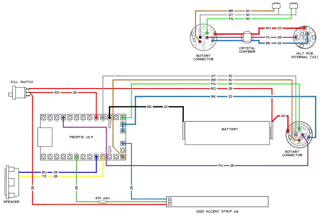
So I have, what I thought what was going to be, a build schematic – apologies for the rough and readiness… Presentation1.pdf (168.6 KB)
I know the LED is wired correctly and I omitted the speaker because I know that is wired correctly. But the other aspects, I’m not sure about. I will note that I used the Proffie configuration tool and I have included the button schematics from the manufacturer.
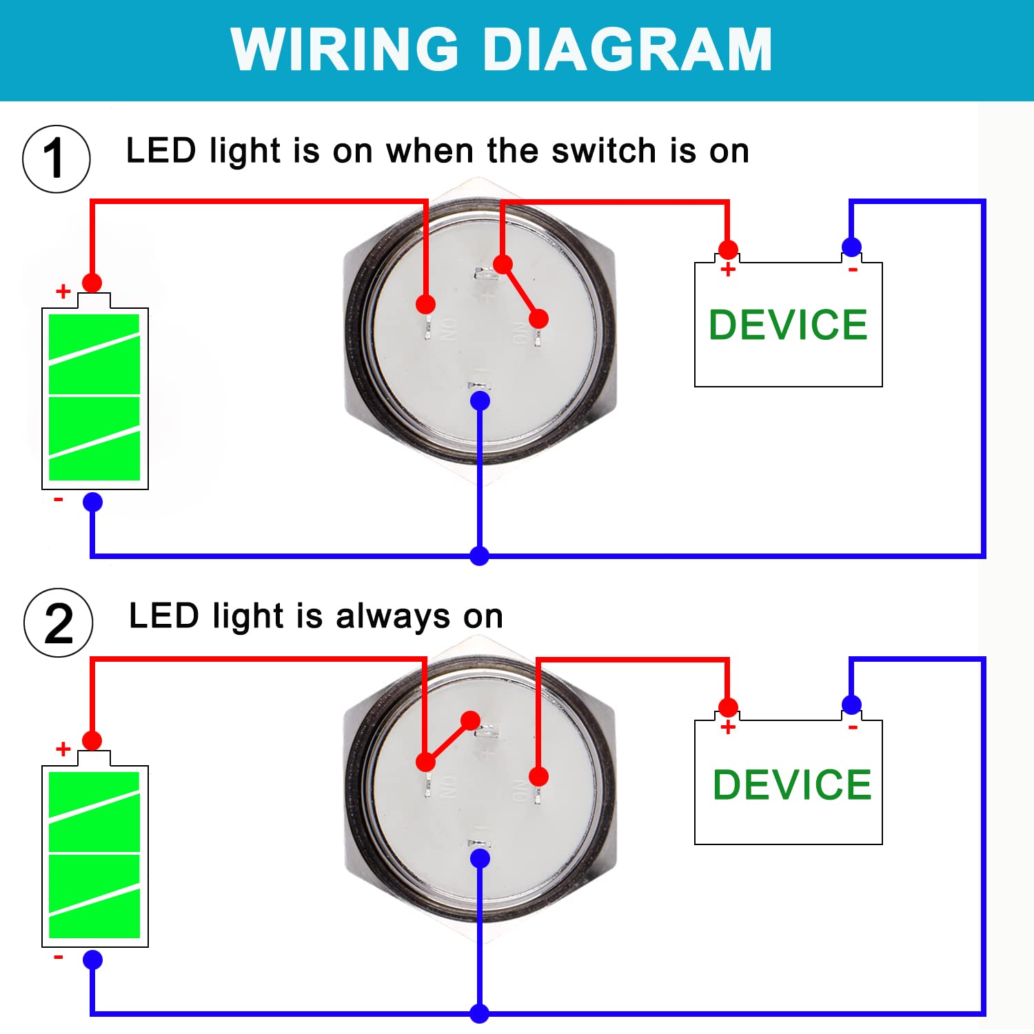
An illuminated switch is a LED and a switch.
In your wiring diagram the “switch” part seems to be hooked up between FREE3 and BT1, which doesn’t work. The LED is hooked up between GND and BT1 (assuming the blue line is connected to two pins on the button component) which also doesn’t work.