try to attempt the first build, and got stuck on this PCB connector.
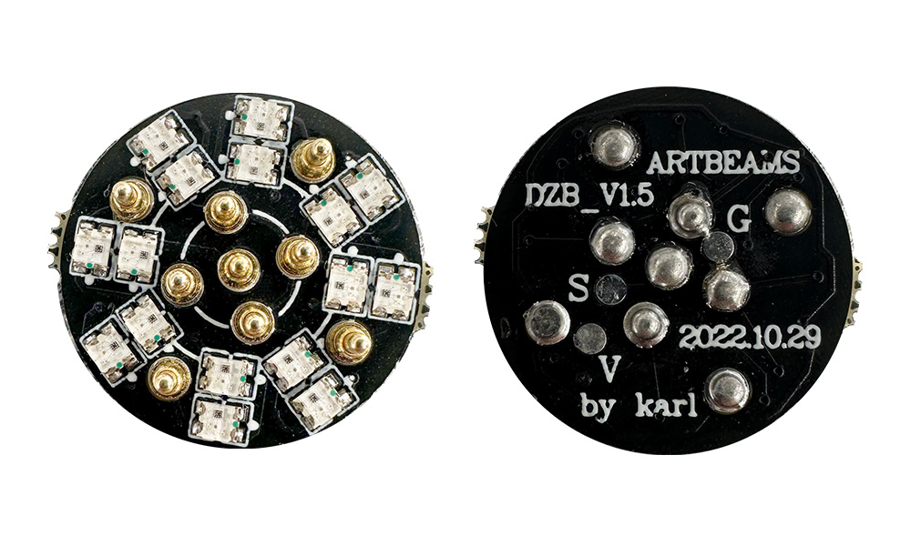
I bought this connector for my saber, it has 16LED, do I need to count the 16 pixels and plus it on the total blade number? On the PCB it prints Artbeams DZB_V1.5 by Karl, it only shows the letters G, S, and V. And I couldn’t figure out where is the Data, positive, and negative pads. Does anyone know? Neeeed Help…
Ideally, the seller will have information about the PCB.
If not, try posting a picture of the PCB so that people can see what you’re talking about.
Never seen one of those before.
Not sure what S and V stands for.
Neither Google nor Bing seems to know anything either.
Guess you’ll need to measure what is connected to what.
1 Like
Usually V is used for volts (positive) and G will be used for Ground and S for Signal. However without the schematic to verify that there is now gaurantee
1 Like
Thank you, Prof, I want to change this PCB to NPXL V3 which has more pads and pins, is also more popular, and has a manual for it.
Thank you for solving my question, I believe you are right!
You could always just solder to the pins directly ![]()
yes…but I do not have any welding experience, welding errors need to be unwelded, I am still learning that. ![]()
![]()
Failure is the best teacher.
3 Likes
Thank you for your encouragement!
1 Like
Artbeams was an etsy store that sold knockoff PCBs. That’s their version of the NPXL V3. I came across their name while trying to find the 89Sabers 13 pin chassis connector. I believe they got shutdown for IP infringement.
Thank you for letting me know, I can’t find 89sabers 13 pin chassis connetor anywhere either.