How to wire a 3.5mm jack to mono, and can it be swapped with a speaker?

Basically, I managed to blow a speaker. When something breaks though, it means it can be improved. I’ve wanted to wire in a 3.5mm (1/8 inch) aux port for audio out so I can record the sound on my PC, but I was also thinking about allowing it to be removed and replaced with a speaker.

So, first question: How do I wire an aux port to a saber? I checked the proffie manual and there was nothing about audio jack speaker replacements or wiring. Do I have to wire it to mono, since the output is mono? Has anyone here actually wired one that can give me some tips?

And my second question (which is redundant if the aux port requires more than 2 wires); is it possible to use a 2-pin connector from TheSaberArmory (like this) to allow a swappable aux-port to speaker system?

Obviously I’d need to change the volume in the saber config when I do this but I’d like to not have to unsolder and resolder every time i want to swap. Any info would be great!

Proffieboards use a class D amplifier to output sound.
That means that the output is actually a 400kHz PWM-like signal. The speaker coil acts like a filter and smooths out the signal into something that actually sounds pretty good. Depending on how the audio input works on your PC, you may or may not need something to do this filtering to make it work well. The speaker output on the Proffieboard is about +/- 5 volts, which is about 10 times higher than an AUX connection, so a 10:1 voltage divider would be recommended. Also, you probably want some 1uF capacitors on both the ground and on the audio signal to prevent ground noise.

It may be worth noticing that Proffieboards also support I2S and SPDIF output. An optical SPDIF output only requires one component (the jack), and there is no chance of any electrical damage or interference.

Using a two-pin connector of some sort to swap between an output jack and a speaker should work just fine. (Assuming you get the output jack to work ok in the first place of course.)

Oh, and yes, you should wire the jack for mono, meaning the middle ring should be hooked up to the same signal as the tip.

Hmm. I’ve not heard about voltage dividers and capacitors being used (I’m not an expert though and have zero experience) but I’ll have to do some research and ask some installers. I’ve also heard that you have to turn your config volume way lower than the standard speaker to prevent unwanted noise. Does this provide a similar effect to the capacitors and divider? Or is that a completely different thing entirely?

Lowering the volume would do something similar to having a voltage divider.
If I was hooking it up, I would do it something like this:

SPKR+   -----[ R=1k ]------+---------||-------------> JACK +
                           |         1uF
                       [R=220]
                           |         1uf
SPKR-   ------[ R=1k ]-----+---------||------------> JACK GND

Note that this is completely untested, and I’m NOT an audio engineer, so this might be all kinds of wrong. But the idea here is to protect both the PC and the saber from each other with capacitors, and to lower the voltage down to something that is reasonable for an AUX jack. You might still need to fiddle with the volume, and possible with the component values as well, but it’s what I would do…

As the Prof says, this is entirely do-able, and I’ve done it myself, but it is kind of a hack rather than a fully supported feature.

I work as a Sound Supervisor on TV shows, although I’m more an operator than an engineer. But in very basic terms, in a professional environment, analogue audio works at different levels as follows:

MIC, LINE and AMPLIFIED

A microphone outputs a very low level known as MIC level. This has to go through a pre-amplifier to be boosted to a LINE level. Once at LINE level, all the audio processing hardware can work with it, such as sound mixing desks, outboard audio processors such as compressors or reverb units etc.

The amount of amplification is controlled using a GAIN control. If you’ve ever used an analogue sound mixing desk, although different desks use different ways to skin the same cat - especially at the budget/domestic end of the market, you’ll have seen that they normally have two distinct sockets on the input to each channel, one labelled MIC and one labelled LINE. MIC is usually an XLR socket, while LINE is often a 1/4 inch jack socket. The MIC input routes the audio through the pre-amplifier, while the LINE socket will bypass the pre-amp or do something else to avoid the already high LINE level being amplified further.

Once all the processing is done, the LINE level gets sent to the power amplifier, which boosts it further to a level capable of driving a loudspeaker. Depending on the amp and the speaker, this level is substantially higher than a LINE level, so much so that people talk in terms of watts when describing the level rather than the millivolts used when talking about MIC and LINE levels.

What you need to understand about what you’re trying to achieve is that the level sent to the speaker on a Proffieboard is essentially at loudspeaker level, i.e. the highest level in the chain described above, and what you’re trying to do is drop it back down to a LINE level so you can work with it in other outboard audio stuff. Hence the Prof’s good advice to build some form of protection into your system.

Mono Versus Stereo

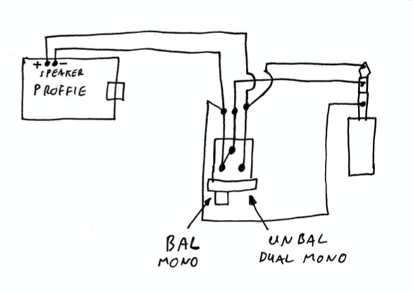
Although perhaps a symantic argument, I’ll go into this briefly as I think it’s relevant and does cause lots of confusion. But as the Prof says, Proffieboards work with Mono audio - how could they do any different with only one speaker? But most domestic stuff such as wired headphones uses a stereo mini-jack. Mini-jacks are also sometimes referred to as TRS jacks, the TRS meaning Tip, Ring, Sleeve. The way these are wired is Tip = Left positive, Ring = Right positive, and Sleeve = shared screen (also known as earth or ground). As such, when making an adapter for the Proffieboard, you’ll need to wire the Proffie speaker positive to the tip AND the ring, and the Proffieboard speaker negative to the sleeve. Note however that in strict terms this does NOT give you true stereo - it gives you dual-mono, i.e. two speakers (earphones) reproducing the same sound, as opposed to true stereo in which each speaker reproduces different sound to create a stereo image or soundscape.

Be warned however that there is one more curved ball that catches people out…

Balanced versus Unbalanced

OK, this is where it gets a little more complicated. In professional studio environments, control rooms can be a long way from studio floors, or in the case of music concerts, the stage is at one end of the venue while the sound mixer is miles away at the other end of the venue. If you tried to run unbalanced audio wired like domestic headphones, i.e. a single positive and negative for each source, the cable would pick up all sorts of horrible hums and the audio would be unusuable. Enter stage right balanced audio.

Balanced audio works by using three cores in the wire for each source, wired in such a way that unwanted hums cancel each other out. This is why XLR connectors used for most microphones have three pins rather than just two. This is also why you will see that the first thing a guitar player on a stage has to do is plug the unbalanced output of his guitar into a DI (Direct Injection) box. This converts the unbalanced guitar output to a balanced MIC level output that will then survive the long cable run to the stage control room without inducing unwanted hums along the way.

The reason domestic audio is generally unbalanced is because the cable runs in your living room are short enough that such hums are unlikely to be an issue. Likewise, there’s no need for balanced audio in a lightsaber because it’s so short. And the reason loudspeaker wires only need two cores (positive and negative) is because the level travelling down them is so high that hums just get blown away by sheer horsepower. (It’s more complex that this, but the analogy is helpful).

So why am I bothering to talk about it? I’m talking about it because many audio input devices use the same connectors for their balanced audio inputs that get used for many unbalanced sources. The classic is the 1/4 stereo jack plug. These are widely used for both balanced and unbalanced audio, but the differences in their wiring mean that people are often surprised when they don’t work as intended in certain hardware.

What all this boils down to is that you need to wire your Proffieboard adapter for its specific purpose. So if, for instance, you want to be able to plug your unbalanced stereo headphones into the saber so that only you can hear it, you need to wire it for duel-mono unbalanced as the Prof described. However if you’re planning on connecting your saber to a live PA system that expects a balanced LINE level, you’ll need to wire it differently.

Again, this is somewhat of a hack, but it does work. So for converting your Proffieboard speaker output to a single balanced output from your saber, you’ll need to wire the Proffieboard speaker neg to the jack screen AND the jack ring, then wire the Proffieboard speaker positive to the jack tip. You will then be able to connect your saber to a balanced LINE level input on a sound system or PC soundcard that has balanced analogue inputs. Note that this won’t be TRUE balanced audio, and as such may or may not survive long cable runs. Rather it is a hack that fools the electronics into thinking that they’re getting balanced audio when they’re not. But in domestic situations, it generally works well.

The really good news is that you can make a simple adapter that will do both using a switch. Leaving aside the Prof’s safety measures, the wiring would be as per the sketch below. But as the prof mentioned, with any kind of adapter of this sort, you’ll need to lower the volume of the saber to something the audio system can cope with to get the best results.

Hope that helps.

:slight_smile:
Screenshot 2022-11-08 at 10.17.48

3 Likes

or just use a tip/sleeve plug

Thank you for spending so much time going in depth. Seeing as I don’t think I’ll need a balanced mono, I’ll probably stick with the prof verison. I went to my local radioshack and picked up the resistors and capacitors (although they were out of 1uf capacitors so I had to get .1uf, was told they might work but if not they can get 1uf in stock soon) and now I’m just waiting on my speaker and extra bits to arrive from TheSaberArmory. I’ll keep you posted on updates, but for now I need to wait. I could test the aux now and just wire the speaker ‘section’ up later…

I seriously appreciate the help. Hopefully it works, i spend like $60 on just basic electronics and a 25 foot aux cable lol.

For what it’s worth, let me just say that most, if not all the setups I’ve seen / done are simply hardwired speaker + and - to an audio jack and plug it in. Works.

In my case, I wired to a female 1/4" mounted in the bottom of the pommel, and use a wireless guitar xmit/recv and works great. I for one am all for proper science applied to a project. I am also one who enjoys this crude but true life lesson :slight_smile:

-tinyurl.com/22ls7wue

I got it set up with normal wires for now just to test, because my connectors aren’t going to be here for a while. Testing is now underway!

Edit: after some testing I think something is up with either my board or my wiring. When a battery is placed in the saber, the area around the speaker pads starts to heat up… That’s never good. I’m concerned that either my wiring was bad, or that the speaker wasn’t actually bad and that my board had a failure somewhere… I’ll check tomorrow cause it’s late but dang.

0.1uF is probably too small.
Anything 1uF or bigger should work I think.

I bought some 10uf ones to try first, and if that doesnt work i’ll try the .1’s but I doubt I’ll have to. I’m checking for board damage currently as I have a suspicion that the speaker isn’t actually blow and that something went bad or got damaged. It’s an older board that I did lots of testing with and it was my first install board as well, so the chances of me damaging it somewhere along the line is pretty high.

Edit: i was right, the speaker works just fine when put in another saber. I think my board is toast… Luckily I have a donor proffieboard from my first LGT proffie saber. Used it so much that the button is worn and barely works, plus i accidently severed one of the wires to the charging port and I never use the saber anymore nyway so it’ll be a suitable donor.

wiring up the capacitors rn, should the positive be wired toward the aux? I’m new to capacitor wiring and want to make sure.

Also, I got the board swapped and after a test of the non-divided aux wired straight to the board and it sounds like garbage even with the volume turned down. I have a suspicion it’s the aux port I got but I’ll have to see.


Here’s the audio recorded without the divider setup. Volume in the config is set to 50, and it sounds like this? Recorded as a mic input directly into audacity. Maybe it’s my settings?

I have a suspicion it’s the aux port I got but I’ll have to see.

WELL WELL WELL. It’s the aux port this time, apparently the port I got doesn’t fully seat for some reason. I’ll have to pick up a new one tomorrow.

I’m guessing that you are using electrolytic capacitors if they have a + and a -?
The circuit I made doesn’t have a + and a -, and I also wouldn’t recommend using electrolytic capacitors in it. The input for the capacitor varies, and can be both positive and negative, and electrolytic capacitors don’t like that. Putting a negative charge in an electrolytic capacitor damages it. Most other types of capacitors don’t care an can be charged either way. (Which is what my circuit assumes.)

No idea what makes it sound bad though. My guess is that the sound card doesn’t have the filters needed to smooth out the PWM. If that’s the case, then an RC filter with a cutoff-frequency near 50kHz could be added to make the circuit work better.

Also, beware that even if don’t have a filter or voltage divider, the output will still be +/- 5 volts for short amounts of time, regardless of what volume you specify, which could potentially overload or damage a sound input.

1 Like

got it wired up, but most importantly i found out what was going on.

My pc has an ‘enhanced audio’ setting that is defaulted to ‘on’ on every mic, including the saber. ‘Enhanced’ audio pretty much destroyed the saber sound quality.

I would highly suggest NOT using a MIC input, as that’s the opposite extreme of AMP level signal that’s coming out of the board. There are AMP-> LINE level converters available, typiclly used in the car audio industry, where people take their rear speaker signal and use it as input to a subwoofer amp where it gets crossed over low.
You really want a line-level input, and I would suggest some DAC that does analog-> USB.
Something like this:

2 Likes