Hi, folks! I just purchased a KR Sabers Luke ECO with master chassis and am currently planning my install. This will be my first install, however, I do have some prior soldering experience as I used to maintain a vintage arcade cabinet. I think I have the wiring diagram figured out (I may post it here to get feedback). What I am really wondering is how you test your work as you progress? Obviously, I don’t want to get everything glued together and find it not working, right? Sorry for such a basic question. Thanks in advance!
IMHO, the most important part is to check your soldering. Usually this is a two-step process:
Visually inspect with magnification to make sure it looks good.
Use a multimeter to check for continuity between the soldered parts, and also check that there is no continuity to any nearby parts. A single strand of copper can be hard to see in some cases, but the meter will tell you.
Secondly, I recommend testing-as-you-go. This means check that the board works before you solder. Each time you solder something to the board, make sure that it works. Speakers, buttons and blades can all be tested individually. It’s a lot faster to just solder everything up and then test it, but it’s also a lot more painful if something goes wrong.
Does that mean that you want to have the proffie board programmed before you begin assembly? And then what about power to the board? Should one use a battery pack with leads?
You just have to program something on the proffieboard, doesn’t have to be anything like the final programming.
For battery power; it depends. My sabers usually use JST connectors for the batteries, but sometimes there isn’t room for that, and obviously you don’t really need it if you’re using a battery holder of some sort, because you can just remove the battery.
I guess knowing what to expect is key. If you test the speakers on USB-power only, it might not sound very good, but that’s normal, and you can’t test the blade(s) without battery power, so that has to be soldered up first.
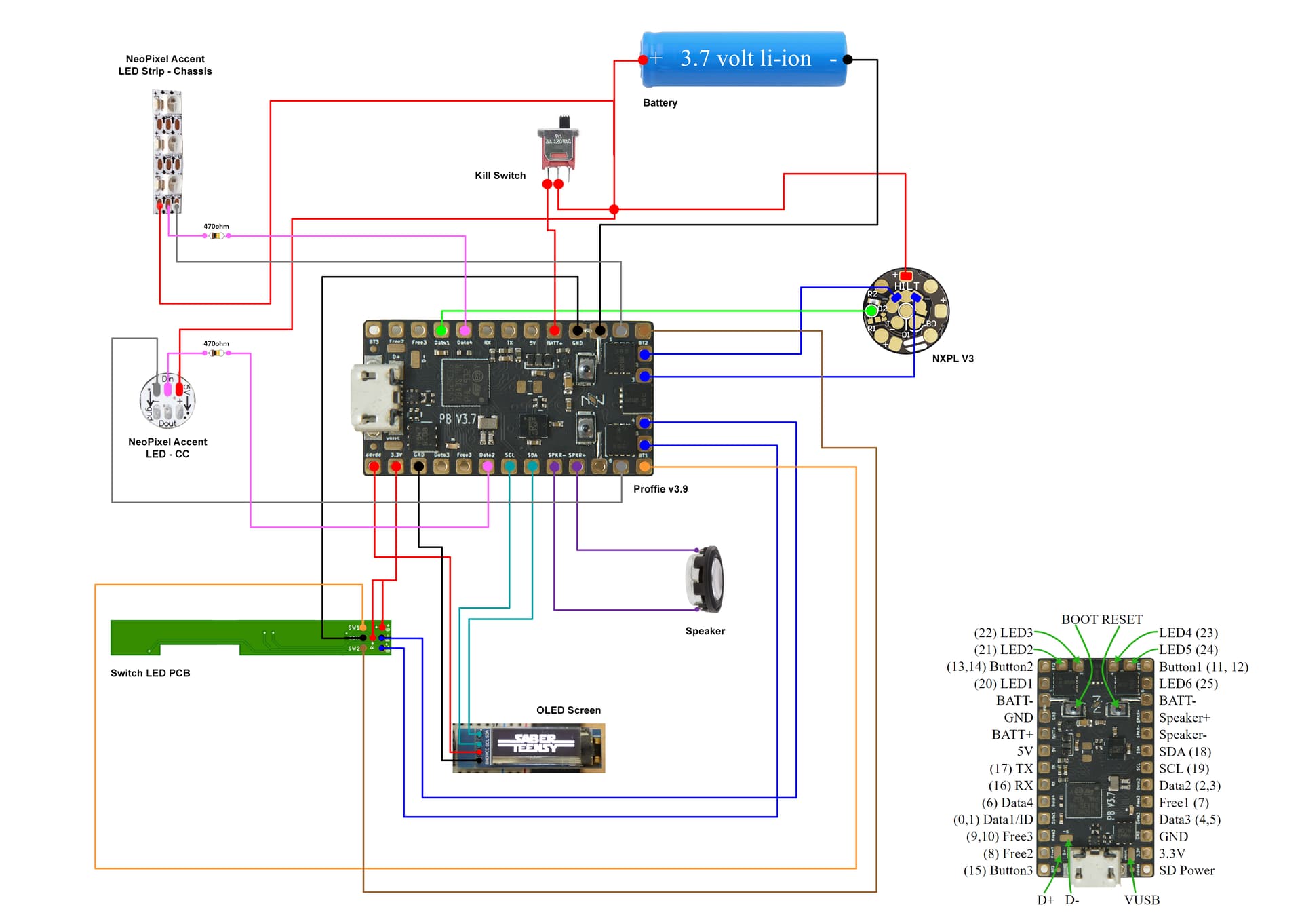
Thanks for the info, guys. Here is the wiring scheme I came up with based on info from KR Sabers and a couple other sources. Does this look OK to you?..
It looks reasonable to me.
I don’t know anything about your switch LED PCB, so I cannot verify those connections though.
It may be beneficial to move the accent LEDs + feed to after the kill switch. (The blade should still go before the kill switch though.)
Thanks, prof! The PCB specifics were taken directly from KR’s instructions, so I can only assume they are correct. I do know that there is one green and one red LED and there are resistors on the board. I appreciate the help!
I was also wondering if neopixel accents need resistors on the data lines. The wiring diagrams indicate a 470 ohm resistor, but I’m seeing many installers omitting them. In my case, the LEDs in question consist of a single Adafruit 5050 for the crystal chamber and a 5-pixel WS2812 2020 mini LED strip for chassis accents. Do these need resistors, or is that primarily for the blade?
The short answer is; maybe
Often, it works just fine without the resistors, but sometimes you get glowy pixels that won’t turn off properly. When that happens, you need the resistors. Whether you actually need them depend on what kind of pixel it is, how it’s wired, and the styles used, so it can be hard to be sure. Most of the time it’s easier to just put the resistor in there and be done with it.
Another thing to test is how the parts are fitting together, and how the chassis sits in the hilt. I just installed goth3d eco cc chassis in an Obiwan hilt as my first full kit (I usually make my own simple chassis or just use electronics shields). It required developing some assembly skills. Mostly sanding with extreme patience and testing and retesting the fits.
The wiring is also very specific in terms of space for some chassis, so I couldn’t use silicone wire that I usually prefer. Every PTFE wire had to be cut to spec, like completing and un assembled model kit. The resistors needed to by heatshrinked on the sides because the tolerances were so tight and if it covered the whole resistor it wouldnt fit Basically I wired the whole thing and couldn’t seal it all up because I had and extra 1/4-1/2 inch of wire creating pressure on the components.
And this time I took the Profezzorn’s advice and checked for continuity everywhere as I went along, and for voltage on the battery tabs. I also usually just use JST connectors.
I’m am so glad I followed the “always use E6000 rule” for glueing. The entire kit was assembled, then disassembled…the E6000 allows for good hold, and slow careful removal if needed.
So I recommend cutting and shaping your wires, filing and fitting everything together with a few parts soldered to their wires, then planning your order of assembly with KR’s instructions and the Goth3d instructions for the master chassis as a guide.
Lastly, get to know the hilt. I was getting frustrated that my chassis kept snagging one of the buttons, then later realized the plunger was threaded and had depth adjustment.
A fascinating and rewarding project that took a good deal of time because of how much there was to learn and how precise the soldering becomes as you progess.
Curious - why should the blade be direct connected to battery? Is it because of amp draw? Is a so called “high amp kill switch” ok, if amp draw is the issue?
how many amps is it rated at? Generally, full white LED strips can draw up to 10A or more, while most killswitches are rated at 3A.
Well, the ones I use anyway. https://tinyurl.com/27ttwg5e
Yeah so just put the switch on the (+) going to the board. I guess there’s still drainage though if the FETs not off totally because the battery->blade->FET->ground->battery, but it should be?
The idea is to reduce power through the switch.
Power ratings for kill switches are complicated. The switches most people use are rated for 3A@150 volts, but can handle a fair bit more since the voltage is much lower than what the switch is rated for, and also because we almost never turn the switch on/off with full power going through the switch. However, it’s not really known how much more. Obviously it’s working for people, but I don’t think anybody knows how close we actually are to the limits of those switches.