This looks reasonable, although it would be better to have a separate resistor for each LED. It’s difficult to know if the LEDs are getting the right amount of current this way. Also, you have to know the forward voltage for the LED inside the switch to calculate the right resistance.
SInce it’s wired to be controlled by LED5/LED6, it’s entirely possible that the reason the purple one doesn’t light up is because of a problem in the config file.
What does your config file look like?
I had Brian Conner from the proffieboard support group help me write this.
struct PurpleLED {
static constexpr float MaxAmps = 0.02;
static constexpr float MaxVolts = 3.0;
static constexpr float P2Amps = 0.10;
static constexpr float P2Volts = 3.0;
static constexpr float R = 220; // Resistor value
static const int Red = 255;
static const int Green = 255;
static const int Blue = 255;
};
BladeConfig blades[] = {
{ 0, WS281XBladePtr<132, bladePin, Color8::GRB, PowerPINS<bladePowerPin1, bladePowerPin3> >(),
SimpleBladePtr<RedLED, NoLED, NoLED, NoLED, bladePowerPin5, -1, -1, -1>(),
SimpleBladePtr<PurpleLED, NoLED, NoLED, NoLED, bladePowerPin6, -1, -1, -1>(),
CONFIGARRAY(presets) },
};
#endif
#ifdef CONFIG_BUTTONS
Button PowerButton(BUTTON_POWER, powerButtonPin, “pow”);
Button AuxButton(BUTTON_AUX, auxPin, “aux”);
#endif
At first it wasnt like this but we tried to define the switches separately because the purple one wasnt lighting and it still didnt fix the issue.
A few observations:
- the PurpleLED struct isn’t specified for a white value. That might be confusing. Maybe try setting ‘Green’ to 0.
- The MaxVolts and P2Volts are the same which isn’t right and could lead to a division by zero in the code. (I’m not going to dive too deep into this, keep reading to find out why…)
- The LED struct logic assumes that your LED is powered by the battery and isn’t really helpful when powering the LED from a fixed power source like the 3.3v pad. So really we should just nerf all these values.
- Read this: Recommended way to post a config file
Anyways, here is what I suggest trying:
struct PurpleLED {
  static constexpr float MaxAmps = 0.02;
  static constexpr float MaxVolts = 30.0;    // nerf it because we're powered by 3.3v
  static constexpr float P2Amps = 0.10;
  static constexpr float P2Volts = 3.0;
  static constexpr float R = 220; // Resistor value
  static const int Red = 255;
  static const int Green = 0;
  static const int Blue = 255;
};
Now if that doesn’t work, we’ll have to look at the styles to see if maybe they are the wrong color?
Thanks ill try it. Im actually completely building a new saber from scratch using the same config, so I do have the option now to solder in individual resistors to the LEDS. The smallest I have are 100ohms. Would I just still try this config or would you recommend just something simpler which have worked previously. I didn’t expect wiring two LED switches to be such an issue. haha
Not sure if 100ohms is enough, it depends on the LED.
The resistance you need is \frac{ 3.3 - LED voltage }{ LED current } So if your LED has a forward voltage of 2.3 volts and it wants 20mA, you get \frac{3.3 - 2.3}{0.02} = 50 ohms. A bigger resistor will always work, but it will make it less bright. Smaller resistor can burn out your LED.
The calculation above doesn’t really work properly if you have two LEDs on the same resistor though, and the brightness of one LED will vary a bit depending on whether the other one is on or off.
If I recall, the RedLED and PurpleLED were set up differently based on the Vf you stated, but I’m foggy on it, and you didn’t post the Red above…
Interesting @profezzorn that white wouldn’t be correct for a single color LED?
I thought it would basically light up on any color that way.
I’m all ears for how to get this right.
I did always think the single resistor was a bit wonky, but you already had it wired like that, remember Tak? I questioned myself on that in our posts.
A LED configured for white will only light up for white colors, perfect for flash-on-clash, but probably not what we want here.
Of course, however I did build the button LED blade styles to just use White.
That should work.
the forward voltage of the Red led is 2v and the Purple is 3v. so the red LED would need 65ohms and the purple would need 15ohms? I believe that is correct however I only have a 100ohm resistor. I dont mind the LED being dim, i just want it lit. The 220ohm resistor i had was in series to the parallel LEDS. But sharing 3.3v to 2 LEDS in parallel, would I even need a resistor? I suspect that the reason why my purple LED wasnt lighting was because there wasnt even enough voltage after the drop from my 220ohm resistor to push the diode open on the purple switch.
youre correct, i forgot to post the red led config. let me send it for you.
struct RedLED {
static constexpr float MaxAmps = 0.02;
static constexpr float MaxVolts = 2.0;
static constexpr float P2Amps = 0.10;
static constexpr float P2Volts = 3.0;
static constexpr float R = 220; // Resistor value
static const int Red = 255;
static const int Green = 255;
static const int Blue = 255;
};
struct PurpleLED {
static constexpr float MaxAmps = 0.02;
static constexpr float MaxVolts = 3.0;
static constexpr float P2Amps = 0.10;
static constexpr float P2Volts = 3.0;
static constexpr float R = 220; // Resistor value
static const int Red = 255;
static const int Green = 255;
static const int Blue = 255;
};
BladeConfig blades[] = {
{ 0, WS281XBladePtr<132, bladePin, Color8::GRB, PowerPINS<bladePowerPin1, bladePowerPin3> >(),
SimpleBladePtr<RedLED, NoLED, NoLED, NoLED, bladePowerPin5, -1, -1, -1>(),
SimpleBladePtr<PurpleLED, NoLED, NoLED, NoLED, bladePowerPin6, -1, -1, -1>(),
CONFIGARRAY(presets) },
};
#endif
#ifdef CONFIG_BUTTONS
Button PowerButton(BUTTON_POWER, powerButtonPin, “pow”);
Button AuxButton(BUTTON_AUX, auxPin, “aux”);
#endif
Lets say i just want 1.5v going to both my LED’s i would actually just need about 90ohms in series and then my they would share the remaining 1.3v. so probably my 220 ohm was just way too much resistance, so my purple wouldnt light. Ill put it on a breadboard to test it out.
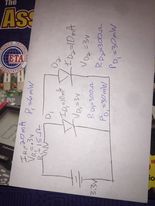
That pic is thumbnail size and not resizable. Use https://postimages.org/ and copy paste the “Direct Link” URL here instead.
Yeah these are incorrect. Not sure how to get these values without a bench power supply.
The problem here isn’t the 220ohms, It’s the other LED.
LEDs have a weird relationship between volts and current.
It looks something like this:
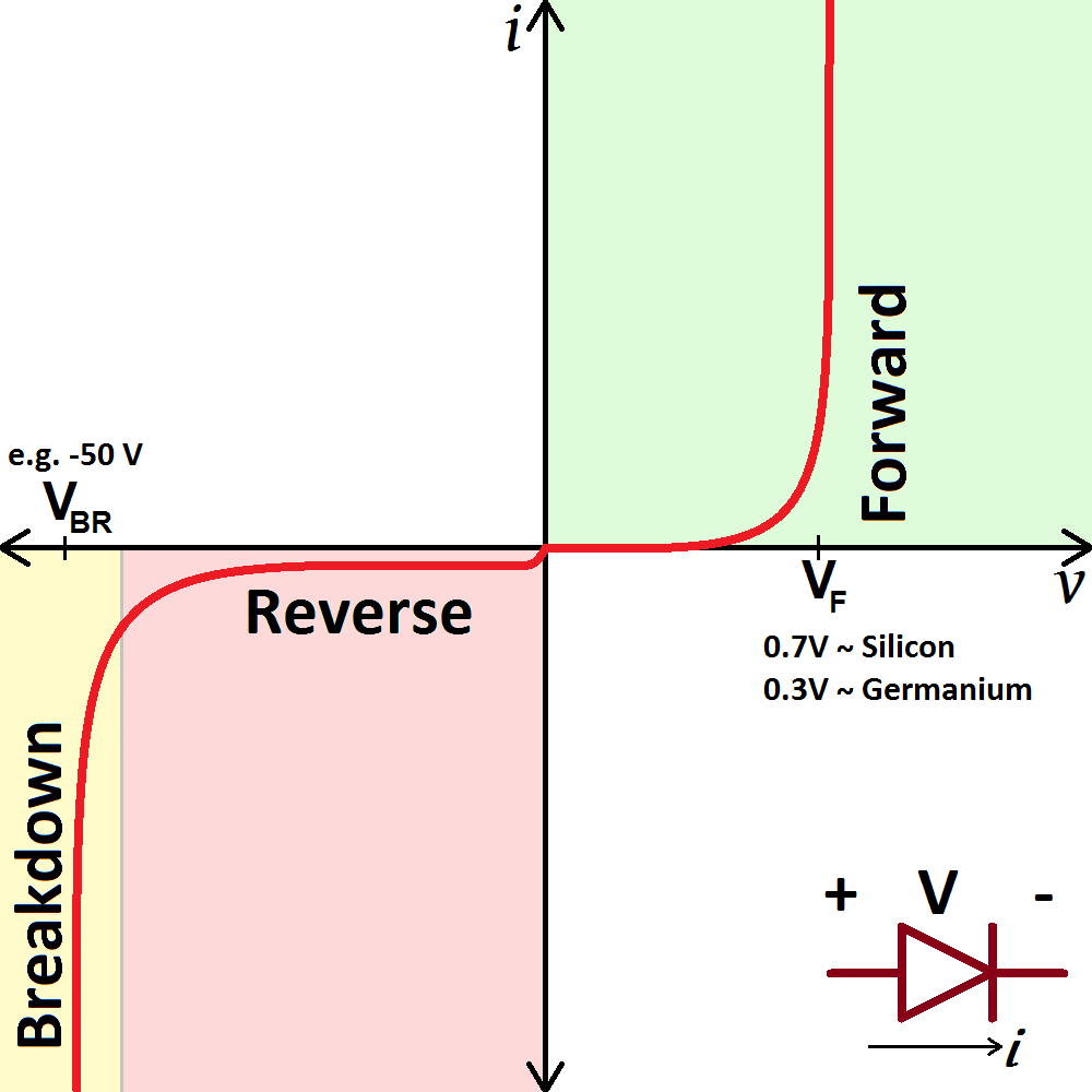
For a LED, we can ignore the red quadrant and focus on the green quadrant.
It’s important to note that the current red line is very very steep near Vf.
What it means is that if the voltage is lower then Vf, you get no current, and in most cases the voltage across the diode will stay at Vf.
This in turn means is that if you hook up a diode to a 220ohm resistor. (which is more than you need) the diode will still stay very close to Vf. So if Vf is 2.0 and you feed in 3.3v, you will have about 1.3 volts across the resistor, which means that there is about \frac{1.3}{220} = 6 mA going through the circuit. Not a lot, but enough to light up the diode.
Now, if you hook up another diode next to it, but with a Vf of 3.0 volts, because 2.0 volts isn’t enough, and the diode has no way to raise the voltage. All the current will just bypass the diode with the higher Vf and go to the one with the lower Vf.
Now, if the diode with a Vf of 2.0 gets turned off. The other diode will suddenly be alone on the circuit, and would settle around 3.0 volts. The resistor would have 0.3 volts and the current would be \frac{0.3}{220} = 1.36mA again, not much, but the LED would light up a bit at least.
I’ve used resistors up to 4.7k with diodes. They become pretty weak when you do that, but they sitll glow a little.
Why use postimages? Just drag-n-drop the picture into the forum.
Hooking up LEDs in series works just fine as long as there is enough voltage for them to share, but of course you can’t control them individually if you do that.
If you leds have Vf = 2 and Vf = 3, you would need at least 5 volts to hook them up in serial.