Following up with @profezzorn on the side-issue from my previous post concerning five Tritium boards that were acting mysteriously.
While they would continue to boot-loop without the SD card inserted, they now flash 100% ok with a card installed and whatever ended up resolving my previous issue now resolved. They act completely normally as long as the card is in; I can unplug and re-plug and re-flash to my hearts content with absolutely zero issues.
Here’s the but… All but ONE of them acts completely normally. The fifth one is not recognized by the computer WHATSOEVER… plugging it in via USB does the exact same as sitting the board next to the cable. No chime, no Proffieboard displaying in the Devices and Printers menu. Absolutely zero response.
However, forcing bootloader DOES allow me to flash and I verified that the config did indeed take (tacked speaker wires and probed battery pads with a wired battery and got the expected boot sound). That said, it displays the same behavior when plugged back into USB after the successful flash.
Anything I can check to figure out what is going on here? If not, it seems at this point that worse case scenario would be that I need to keep that board set aside for a build where I have guaranteed access to the buttons at will.
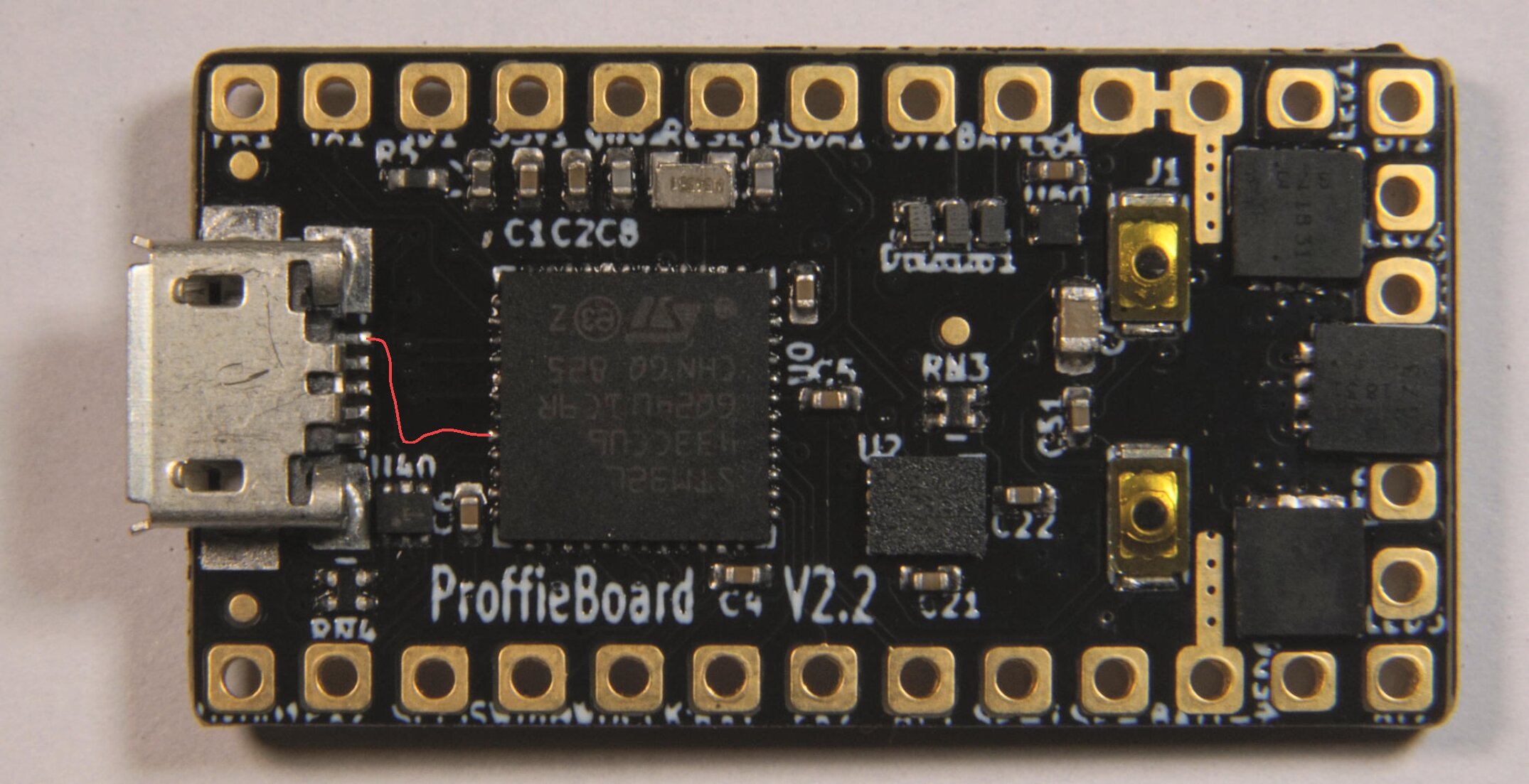
It could be a problem with VUSB somewhere. VUSB is the 5V that comes from the usb connector. VUSB is hooked up to two things:
D62, from here it goes from the 3.3v regulator which provides power to the CPU and other things.
The VUSB sense pin on the CPU.
Now, ProffieOS normally keeps the USB circuitry OFF until it notices voltage showing up on the vusb sense pin, then it fires up the USB circuits and talks usb. The bootloader doesn’t do this, it just fires up the USB circuits right away.
If your board is under warranty, I would suggest contacting tritium and see if you can get a replacement board.
Maybe, but you would need super-pointy test leads and magnification.
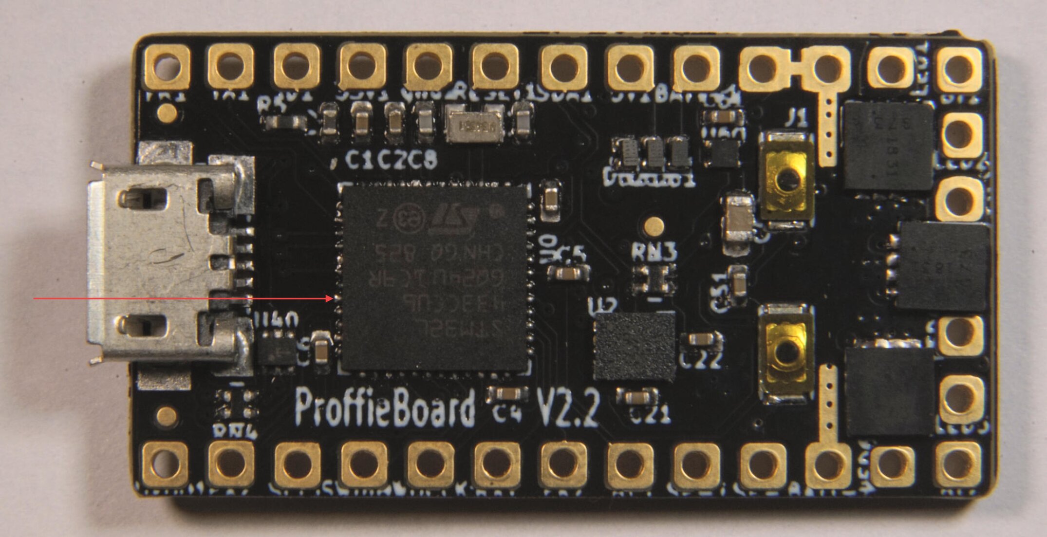
If my theory is correct, then this pad on the CPU doesn’t connect to the PCB properly:
In either of these cases, is it worth a reflow? That is to say, could there be any more related issues that haven’t yet presented since it’s not installed in a saber yet?
Otherwise, I was just going to sit this one to the side and use it in a build where I know I will have guaranteed access to the buttons in case I need to reflash. I got all five of them beand new but secondhand, so I’m guessing my ability to warranty it is pretty nonexistent.
They are diodes, not capacitors.
Not sure why, but it’s fairly common for them to behave weird. Maybe my footprints aren’t right, or maybe those diodes are meant for a different kind of solder or something…
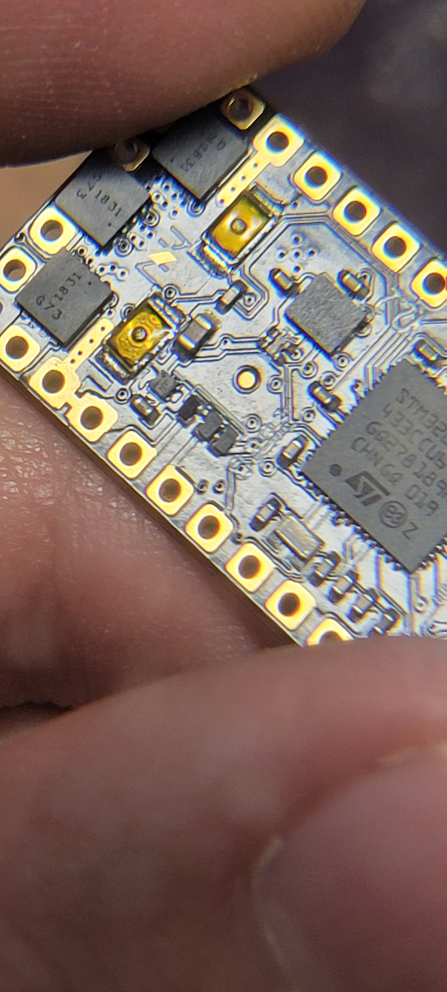
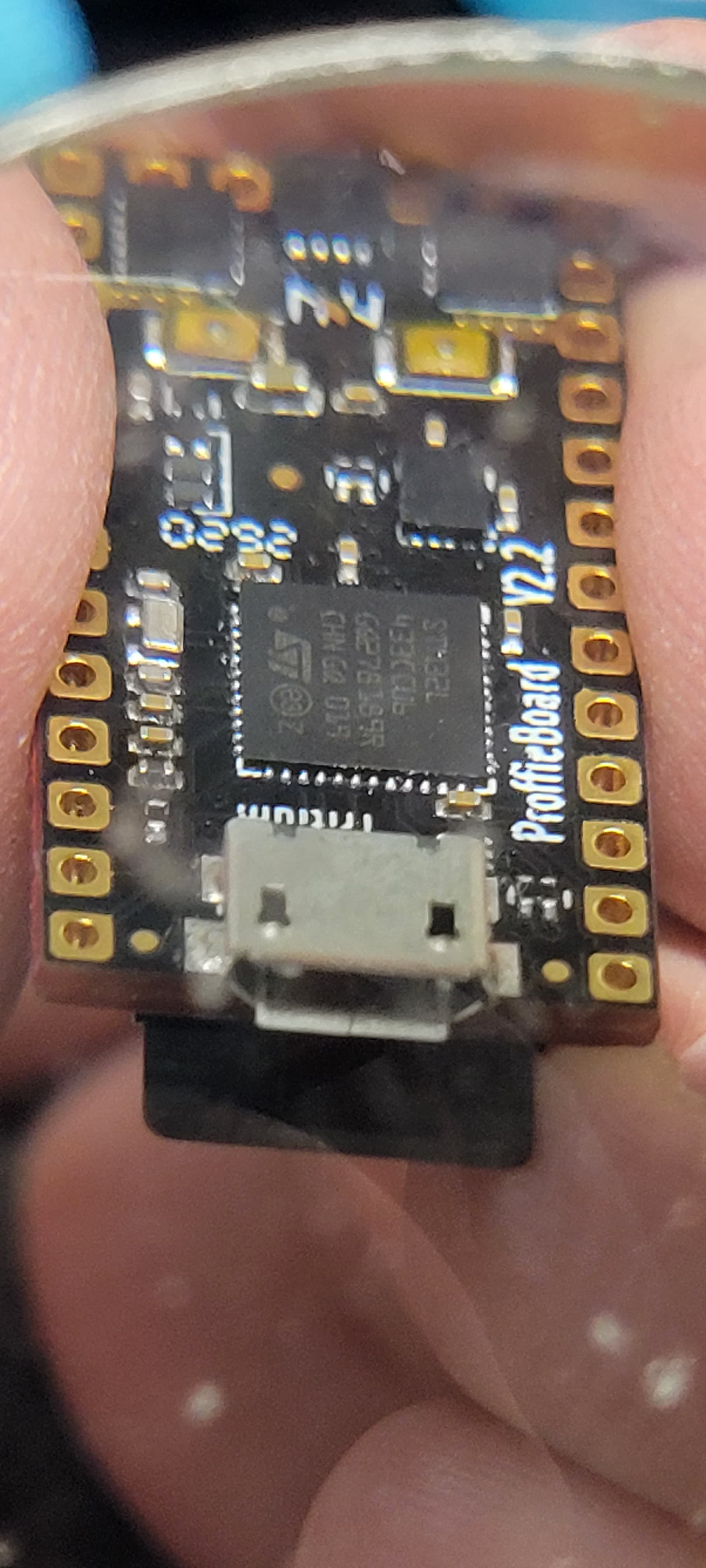
I can’t tell from the picture. The picture looks reasonable to me.
So, most things are tested when the board is made. If you reflow or replace components, you may have to do a lot of testing since a reflow may cause a short or break a connection somewhere.
If it was me, I would check the theory first by measuring the connection between the cpu pin and the VBUS pin on the usb jack. If the connection seems good, then clearly there is no point in re-flowing. But I have a microscope and very pointy test probes I can use.
It’s also possible to modify the software to ignore vusb and run the USB circuits all the time. It’s a little bit involved since that code lives in the arduino-proffieboard plugin, but it is possible. The result would be worse standby time, but not enough to matter if you have a kill switch or key.
Gotcha. My probes aren’t fine enough to get into the USB port, and it sounds like attempting to reflow won’t be worth the potential hassle. In the end, the problem is overall inconsequential as long as I’m paying attention. I marked the sides of the PCB with a red sharpie so I know not to use it if I won’t be able to get to the board at will.
Oh, getting inside the usb port is hard.
However, you can either poke the pads in the back, or you can just cut off an usb cable and use the wires… You still need some precision to poke the pad on the side of the CPU though. (And not the pad on the PCB.)
Oh duh, didn’t think of that. Am I following the pin at the back of the MCU straight back to the USB or is it a different one? And am i testing for continuity? Still not positive my probes are thin enough but I can try.
 You still need some precision to poke the pad on the side of the CPU though. (And not the pad on the PCB.)