First Saber Build Wiring check Proffie

Hi all,

got kinda hooked on Youtube saber vids and decided to give it a shot.
I want to build one by myself, since that seems a lot more fun for me than buying a finished product.

I’m fairly new to electronics, so after reading the Proffie manuals and checking the configuration manager i came up with the following curcuit.
Would be great if someone could have a look to see if i made some newbie mistakes.

Specs:
SHTOKCUSTOMWORX NPXL V3 HILT SIDE PCB
PROFFIEBOARD V3.9
Hilt: KR Flagship.
Since it only has one 12mm button hole i went for this dual switch.
12MM 'PIXELSWITCH
Switch

Questions:
Do i need a resistor for the switch?
I can’t find any V and mA specs, so i would not even know how the calculate the right resistor.

For the V4 Setup of the blade Connector i have to remove the R1 resistor.
Do i need to bridge the two pads the resistor was connecting previously?

Thanks!

Shorty

The data lines on pixels need a 330ohm or 470ohm resistor to reduce noise in the signal. The PCB might have one already. I’d message Khal and ask, as he’s very responsive. Adding another won’t do any harm though.

For a first install I would simplify it a bit and use the Shtok connector in V2 format. This means the connector will simply do the same thing as the blade, and it only requires one data line yo the Shtok connector, not two, which in turn makes the config easier. The V2 setup requires two resistors on the back of the Shtok connector, but usually they are already fitted when you buy the connector so you don’t have to do anything.

If the switch is a pixel switch, you will need a resistor on the data line. BUT! If that’s the case, what I would do is run the Shtok blade connector from Data 2 and the switch from Data 1. Data 1 has a resistor built in to the Proffieboard, so is great for things like switches and accent LEDs which don’t have their own resistor. Conversely the Shtok connector in V2 (the default) setup already has resistors built it into, so you can safely run it from Data 2 which is not pre-resistored.

What this boils down to is that as long as the two tiny resistors are fitted the Shtok (which they should be by default) you won’t need to add any resistors at all. Just adjust your config to suit. (Very easy - post here if you get stuck on that bit).

The only other thing is you have your battery tabs the wrong way round - the spring tab should be negative. :slight_smile:

Other than that, good luck and enjoy your build.
:slight_smile:

1 Like

Thanks!

ok that sounds good, was a little bit scared of desoldering the small resistor anyways
since i’m just starting with soldering on a practice board.
The config generator default is in v4 thats why i went with it.
Gonna start reading into the config files now to see where i have to make adjustments to meet the updated curcuit.

Blockquote
The only other thing is you have your battery tabs the wrong way round - the spring tab should be negative. :slight_smile:
Blockquote
:man_facepalming: was a little confused with that because most of the battery holders i know have an actual spring for the negative. Looked a little bit wobbly if the button of the battery has to connect to the button on the contact plate. Or are these ment for batterys with 2 flat sides?

At the bottom of your config will be something along the lines of this:

BladeConfig blades[] = {
 { 0, WS281XBladePtr<144, bladePin, Color8::GRB, PowerPINS<bladePowerPin2, bladePowerPin3> >(),
    WS281XBladePtr<1, blade2Pin, Color8::GRB, PowerPINS<bladePowerPin5> >(),
CONFIGARRAY(presets) },
};

bladePin and blade2Pin refer to the data pads for each respective ‘blade’. (Every LED on Proffies is referred to in the config as a blade). So if you want to run the main blade off data 2 and the switch LED off data 1, you’d do this:

 BladeConfig blades[] = {
 { 0, WS281XBladePtr<144, blade2Pin, Color8::GRB, PowerPINS<bladePowerPin2, bladePowerPin3> >(),
    WS281XBladePtr<1, bladePin, Color8::GRB, PowerPINS<bladePowerPin5> >(),
CONFIGARRAY(presets) },
};

And that’s it! Job done.
:slight_smile:

As for battery tabs, as long as the chassis has been designed with the battery holder the correct length, then it works well. It’s the chassis itself that holds the battery in place. If you try it the wrong way round, not only is the battery likely to be too tight a fit, but the protective shrink wrapping on the battery that continues part way onto the negative end might mean you don’t get a proper connection on the raised button on the tab. If that makes sense.

Hey,

ah i see, but is there some kind of mapping table for the pins?
Couldn’t find one in the ProffieOs wiki.

Example:
bladePin = Data1 , blade2Pin = Data2

The Configurator (v3 Board) for example says for Blade detect, wire BD to Free1 (Pin 7) (labeled Free 3 on pcb?) .
And the config shows #define BLADE_DETECT_PIN blade5Pin.
Where can i find the info, that Free 1 (Pin 7) = blade5Pin?

Thanks for your help, really appreciate it!

You’re right about that.

It seems that either you’d have to wire the BD pad on the connector to DATA3 (which is blade5Pin) or change the BLADE_DETECT_PIN to blade7Pin.

@profezzorn What are we missing? If you don’t use both pins associated with DATA1-3, does the bladePin numbering revert (as if each pad had only one pin) making Free1 the 5th bladePin?

My understanding is that any unused data pad can be used as a blade detect pad - you just need to specify it at the top of your config.

So if bladePin (data 1) and blade2Pin (data 2) are already used, you could use blade3Pin (data 3) and add this line to the top of your config:

#define BLADE_DETECT_PIN blade3Pin 

That said, if it were my first install, I don’t think I’d worry too much about building Blade Detect into it, as I like to keep things simple.
:slight_smile:

As for your pin table, is this what you mean:
http://fredrik.hubbe.net/lightsaber/v6/

1 Like

Yeah, that table. Why is Free 1 noted as pin 7, but isn’t blade7Pin coming out of the configurator or otherwise?

Not trying to side track, I was trying to figure out the answer to @Shorty ‘s question and couldn’t fully resolve.

Thanks! :slight_smile:

The mapping is in the proffieboard_v3_config.h file

// Proffieboard pin map
enum SaberPins {
  // I2C
  i2cDataPin = 18,                 // I2C bus, Used by motion sensors  PB7
  i2cClockPin = 19,               // I2C bus, Used by motion sensors   PB8

  // Buttons
  powerButtonPin = 11,            // power button  PB14 + PC5
  auxPin = 13,                    // AUX button    PB13 + PA2
  aux2Pin = 15,                   // AUX2 button   PB15

  // Memory card now uses SDIO
  sdCardSelectPin = 255,

  amplifierPin = 32,              // Amplifier enable pin PH1
  boosterPin = 31,                // Booster enable pin   PH0
  motionSensorInterruptPin = 30,  // motion sensor interrupt PC13

  // No fastled support yet
  spiLedSelect = -1,
  spiLedDataOut =-1,
  spiLedClock = -1,

  // Neopixel pins
  bladePin = 0,                   // blade control, either WS2811 or PWM PA7+PA6
  bladeIdentifyPin = 1,           // blade identify input / FoC
  blade2Pin = 2,                  // PA9 + PB4
  blade3Pin = 4,                  // PA10 + PB5
  blade4Pin = 6,                  // PA4
  blade5Pin = 7,                  // Free1 PB3
  blade6Pin = 8,                  // Free2 PB10
  blade7Pin = 9,                  // Free3 PB11 + PC2
  blade8Pin = 16,                 // also uart PC0
  blade9Pin = 17,                 // also uart PC1

  // Blade power control
  bladePowerPin1 = 20,            // blade power control PA1
  bladePowerPin2 = 21,            // blade power control PB6
  bladePowerPin3 = 22,            // blade power control PC7
  bladePowerPin4 = 23,            // blade power control PB1
  bladePowerPin5 = 24,            // blade power control PC6
  bladePowerPin6 = 25,            // blade power control PB0

  // Free1/2/3 can also do PWM
  // You can drive 20mA LEDs with a resistor from these pins, or
  // hook up an external FET to drive more powerful LEDs
  bladePowerPin7 = 7,
  bladePowerPin8 = 8,
  bladePowerPin9 = 9,

  // Status LED
  statusLEDPin = 26,

  // If there is no neopixels, these can be used as PWM output
  // If neopixels are present, but not on these pins, PWM may still
  // be possible at 800kHz.
  bladePowerPin10 = 2,             // PA9
  bladePowerPin11 = 4,             // PA10

  // Analog pins
  batteryLevelPin = 29,           // battery level input PC4

  chargeDetectPin = 27,           // PA0

  // UART
  rxPin = 16,                      // PC0
  txPin = 17,                      // PC1

  // MiCOM setup
  trigger1Pin = 11,   // power button
  trigger2Pin = 13,   // aux button
  trigger3Pin = 15,   // aux2 button
  trigger4Pin = 7,    // free1
  trigger5Pin = 8,    // free2
  trigger6Pin = 9,    // free3
  trigger7Pin = 2,    // data2
  trigger8Pin = 4,    // data3
};
1 Like

As I understand it, the pin numbers are kind of Arduino core system pinouts which can be assigned to any function in any Arduino-based project. Fredrik (who wrote the ProffieOS system) has then assigned those pins to different functions within the Proffie operating system.

Thanks alot!
That’s the mapping i was looking for :grinning:

Time to dive a little bit deeper into the possible configurations while waiting
for my saber parts to arrive.

Starting config would look something like this with the default font download before getting deepter into fonts and styles.

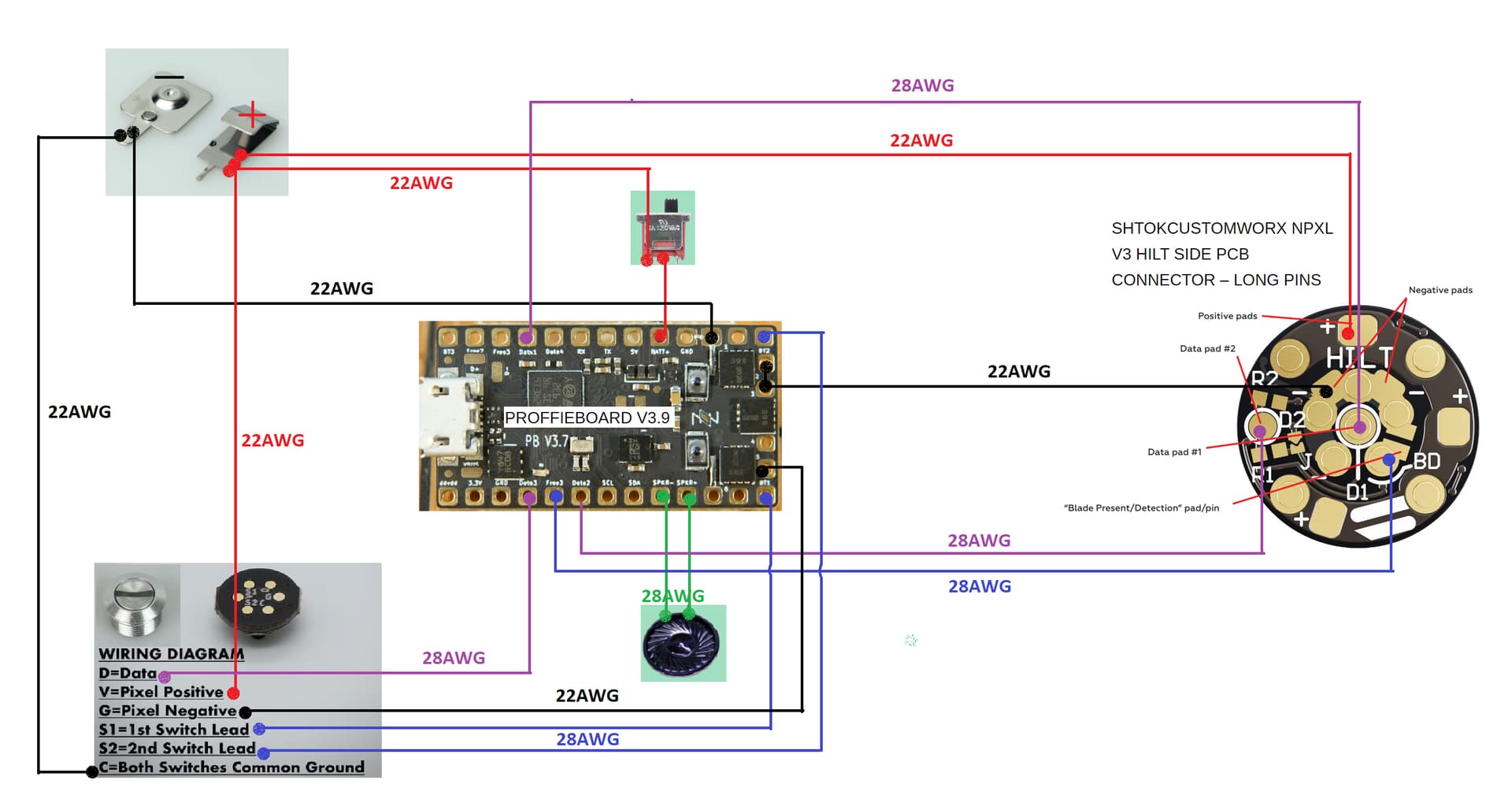
Was a little bit confused why the config generator starts with NUM_BLADES 3 with only the “illuminated pcb” selected (default v4 neopixel pcb config should be 2 blades right? (main + pcb pixel) and in my v2 config 1 Blade because they should be in parallel + 1 Blade for my pixel switch (6pixel).

#ifdef CONFIG_TOP
#include "proffieboard_v3_config.h"
#define NUM_BLADES 2						//v2 neopixel pcb = 1 blade , pixelswitch = 1 blade
#define NUM_BUTTONS 2
#define VOLUME 1000
const unsigned int maxLedsPerStrip = 144;		//To be specified when i build a blade
#define CLASH_THRESHOLD_G 1.0
#define ENABLE_AUDIO
#define ENABLE_MOTION
#define ENABLE_WS2811
#define ENABLE_SD
//#define SHARED_POWER_PINS				not in v2 neopixel pcb config
#define BLADE_DETECT_PIN blade5Pin
#endif

#ifdef CONFIG_PRESETS
Preset presets[] = {
   { "TeensySF", "tracks/venus.wav",
    StyleNormalPtr<CYAN, WHITE, 300, 800>(),
    StyleNormalPtr<CYAN, WHITE, 300, 800>(), "cyan"},
   { "SmthJedi", "tracks/mars.wav",
    StylePtr<InOutSparkTip<EASYBLADE(BLUE, WHITE), 300, 800> >(),
    StylePtr<InOutSparkTip<EASYBLADE(BLUE, WHITE), 300, 800> >(), "blue"},
   { "SmthGrey", "tracks/mercury.wav",
    StyleFirePtr<RED, YELLOW, 0>(),
    StyleFirePtr<RED, YELLOW, 1>(), "fire"},
   { "SmthFuzz", "tracks/uranus.wav",
    StyleNormalPtr<RED, WHITE, 300, 800>(),
    StyleNormalPtr<RED, WHITE, 300, 800>(), "red"},
   { "RgueCmdr", "tracks/venus.wav",
    StyleFirePtr<BLUE, CYAN, 0>(),
    StyleFirePtr<BLUE, CYAN, 1>(), "blue fire"},
   { "TthCrstl", "tracks/mars.wav",
    StylePtr<InOutHelper<EASYBLADE(OnSpark<GREEN>, WHITE), 300, 800> >(),
    StylePtr<InOutHelper<EASYBLADE(OnSpark<GREEN>, WHITE), 300, 800> >(), "green"},
   { "TeensySF", "tracks/mercury.wav",
    StyleNormalPtr<WHITE, RED, 300, 800, RED>(),
    StyleNormalPtr<WHITE, RED, 300, 800, RED>(), "white"},
   { "SmthJedi", "tracks/uranus.wav",
    StyleNormalPtr<AudioFlicker<YELLOW, WHITE>, BLUE, 300, 800>(),
    StyleNormalPtr<AudioFlicker<YELLOW, WHITE>, BLUE, 300, 800>(), "yellow"},
   { "SmthGrey", "tracks/venus.wav",
    StylePtr<InOutSparkTip<EASYBLADE(MAGENTA, WHITE), 300, 800> >(),
    StylePtr<InOutSparkTip<EASYBLADE(MAGENTA, WHITE), 300, 800> >(), "magenta"},
   { "SmthFuzz", "tracks/mars.wav",
    StyleNormalPtr<Gradient<RED, BLUE>, Gradient<CYAN, YELLOW>, 300, 800>(),
    StyleNormalPtr<Gradient<RED, BLUE>, Gradient<CYAN, YELLOW>, 300, 800>(), "gradient"},
   { "RgueCmdr", "tracks/mercury.wav",
    StyleRainbowPtr<300, 800>(),
    StyleRainbowPtr<300, 800>(), "rainbow"},
   { "TthCrstl", "tracks/uranus.wav",
    StyleStrobePtr<WHITE, Rainbow, 15, 300, 800>(),
    StyleStrobePtr<WHITE, Rainbow, 15, 300, 800>(), "strobe"},
   { "TeensySF", "tracks/venus.wav",
    &style_pov,
    StyleNormalPtr<BLACK, BLACK, 300, 800>(),
    StyleNormalPtr<BLACK, BLACK, 300, 800>(), "POV"},
   { "SmthJedi", "tracks/mars.wav",
    &style_charging,
    StyleNormalPtr<BLACK, BLACK, 300, 800>(),
    StyleNormalPtr<BLACK, BLACK, 300, 800>(), "Battery\nLevel"}
};
Presets no_blade_presets[] = {
  { "TeensySF", "tracks/mars.wav", 
   StyleFirePtr<RED, YELLOW, 0>(),
   StyleFirePtr<RED, YELLOW, 0>(),
  "no blade" },

};
BladeConfig blades[] = {
 { 0, 	WS281XBladePtr<144, blade2Pin, Color8::GRB, PowerPINS<bladePowerPin2, bladePowerPin3> >(),
		WS281XBladePtr<6, bladePin, Color8::GRB, PowerPINS<bladePowerPin5> >()
  , CONFIGARRAY(presets) },
 { NO_BLADE, $BLADES$ CONFIGARRAY(no_blade_presets), "nb_save" }
,
};
#endif

#ifdef CONFIG_BUTTONS
Button PowerButton(BUTTON_POWER, powerButtonPin, "pow");
Button AuxButton(BUTTON_AUX, auxPin, "aux");
#endif

The configuration tool splits the pcb leds into two subblades but with a slight difference. SubBladeWithStride let’s you use every second pixel so you end up with an inside ring blade and and outside ring blade.

1 Like

Good idea, I have a pin table on the Proffieboard V3 page, but that table does not include the names given to those pins in ProffieOS, I should fix that.

3 Likes

Hey,

i received my saber parts today .
Right now i’m checking out all the electric parts and the chassi to see how everything fits and where to route the cables. So far everything should fit with some sanding here and there.
Have to say that in person the pcb pads look alot smaller than on pictures and videos :rofl:
Have three questions:

The pads on the pixel switch are very tiny.
The switch has 2 pixels on the pcb so it shouldn’t draw much amps right?
Was wondering if i could replace all 22AWG wires connected to it with 28AWG.

Can i put in the cable for blade detection and not include it in my first config to keep it simple,
but to have the option to tinker with it later. Or do i have to configure it if the cable is connected?

Superglue killswitch , battery contacts and speaker? Or something less permanent?
What aboud the proffieboard. Its not a very secure pressure fit. What would be a good way to secure it.

Thanks!

Yep! :smiley: Buy a magnifier you can wear on your head. You’ll look like the toy restorer on Toy Story, but it will make things much easier. :smile:

You can use 28 or 30awg pretty much everywhere EXCEPT:

  • Battery positive to main blade neopixl connector;
  • Proffieboard negatives to main blade neopixel connector (from the LED power pads 1 to 6);
  • Battery negative to Proffieboard;
  • Battery positive to Proffieboard.

Of these, the first three need to be 22awg or larger, and the fourth one you can get away with 26 awg.

Yep, you can wire it up now but leave it out of the config to come back to it later. :slight_smile:

I’m always cautious about using superglue. It’s too fast and too strong and too unforgiving. I tend to use E6000, but once you have the part in place, use tape or something else temporary to hold the part in place and leave it alone while it sets. I generally leave it 24 hours. This will give you the option to unpick it later should the need arise. :slight_smile:

Good luck.
:slight_smile:

1 Like

4 pack on sale for less that $1 each:

2 Likes

Just bought that e6000 pack. Great stuff just use flux smoke level precautions for the vapor.

I learned about Kapton tape for securing/insulating boards here. Always a good addition to a saber building bench.

Nice, ordered both and some tweezers to help me route the wires.