Extremely bright blade with 3W LEDs inside

I’m designing a low density (about 50 pixels per meter) but high intensity blade. A bunch of individual 3W LEDs will be mounted inside. I made one pixel for the first prototype, to work out the geometry before I start mounting my entire bag of 50 yellow 3W LEDs which I bought for almost nothing.

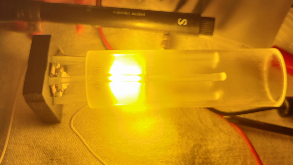
Even with only a single pixel, the thing is painfully bright:

Reducing the current from 600 mA to 50 mA, using a clear (non-diffusing) tube, and countering the LED with the camera flash, we can see what’s inside:

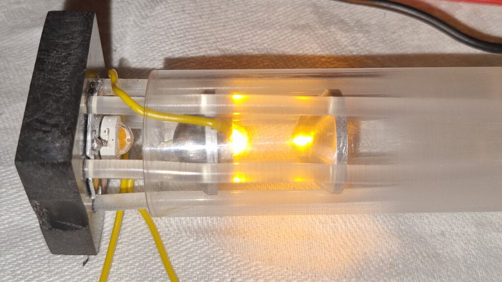
Each LED is mounted on a small aluminium block which has a double role: it provides a heatsink for the LED chip, and the opposite side is parabolic and polished shiny to create the illusion of a second LED, a virtual mirror image opposite the real one. This doubles the apparent pixel density and evens out the light field.

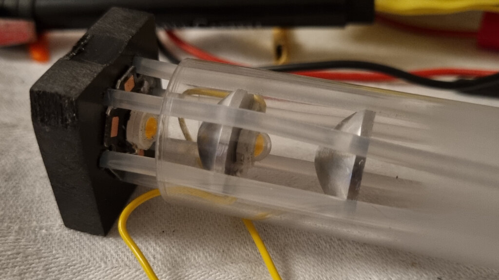
The aluminium blocks are placed in a “cage” of sorts, comprised of six strands of 3mm milky white nylon cord. I would have preferred clear polycarbonate, but I found no source of 2-3mm solid PC rods. Acrylic (PMMA) is easy to find in those dimensions, but it’s brittle, and I want a blade that can take a beating.

The aluminium is not polished to a mirror finish in the images above, hence the considerably dimmer mirror image. A shiny surface will make this a little brighter still.

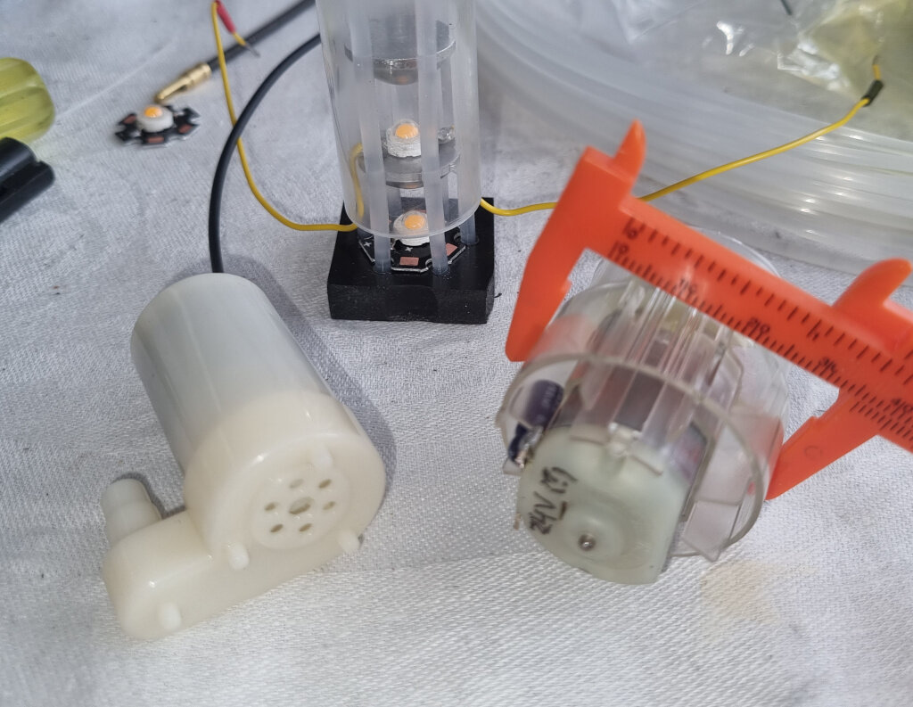
The space between the inner wall of the tube and the aluminium blocks is 2mm on all sides, which allows for a flow of air to (hopefully) keep the LEDs from overheating. It might be possible to run 50 LEDs at full power if I can make a cooling turbo fan that is strong enough, while also being small enough to fit inside a saber hilt. I’m aiming for the clunky form factor, the “Graflex” cylinder shape with 40mm diameter or so, but fitting the cooling fan and enough batteries to power this for at least 15 minutes on one charge will be a challenge.

I have a plan B, which is water cooling. Replace tree of the nylon supports with silicone tubing, pump water through them, and have it flow back around the LEDs. I’d rather not have to make all the electrical connections inside waterproof, though. That’s why it’s plan B. A small water pump is a lot cheaper and easier to find than a small turbo fan, though, and a lot less noisy as well.

Depending on the air resistance (which I think will be fairly high) you might want to consider blowers and aquarium pumps instead of fans since fans tends to be very poor at pushing/pulling air through small spaces. Also, sucking air tends to be slightly easier than blowing air through I think. There are also fans that combine blower-style action with fan-style action which might be good for this, but they aren’t very easy to find I think.

As I’m writing this, another possible design occurs to me:
What if you used laser-cut acrylic to build a plus-shape along the length of the blade.
The plus shape would hold the aluminum pieces in place while diving the space into four chambers. Two of these chambers would be air going up and two would be air going down. The drawback would be that the acrylic would be right in front of the LED, which could make it hot and melt maybe…

With “fan” I meant “turbo fan”, i.e. a blower of the kind you have in hot air guns or blow dryers, or possibly a centrifugal blower. A centrifugal blower is a bad fit for the cylindrical form factor of a saber hilt, but perhaps I can hide it in ornamentation. Or, as you suggest, a vacuum fan. The air resistance is not going to be massive, but certainly higher than what a regular cooling fan would be able to handle. The meager pressure gradient you can get from a non-turbo fan is way too low to generate enough flow if there is this much obstruction in the air path, especially if it has to be small enough to fit inside a 40 mm cylinder.

Aquarium pumps are certainly worth trying as well. Small membrane pumps are noisy, but they can push a surprising amount of air with decent pressure. A small but strong aquarium circulation pump I happen to have already is definitely my primary candidate if I need to go for water cooling.

Using one of the probably very expensive 24V, 20W pneumatic pumps I have in my scrap pile would be a massive overkill with their 6 bar, 10 liters per minute rating, but they do fit inside a 40 mm tube. My smallest hot air desoldering blower has a really good turbo fan inside, but it’s in good working order and way too expensive to scrap for parts. I went shopping for a small USB-powered vacuum cleaner this week, but they seem to have gone out of fashion. (For good reason - they were pretty useless.)

Your suggestion to use 3-D printed acrylic is a very nice idea for the geometry, but again, acrylic is brittle, and 3-D printed parts tend to be structurally weak. I am going old school for this build. Lathe, hacksaw, power drill, files – no 3D printing. Except for the turbo fan in the hilt - that part might be a good candidate for printing instead of hunting for one of the right size with enough capacity.

The build continues, but making 50 of those small plano-convex aluminium disks will take a while, because I’m doing them one by one in a manual lathe.

I think if I was making something like this I would try to simplify it a bit.
If the air could escape at the top of the blade (or or out) then the whole design gets simpler.
Also, I think I would use fins rather than tubes for cooling and current.
I could imagine cutting an L-shaped cut into the fin, to create a “tab”. That tab could have a hole drilled through it, then bent out 90 degrees to accept an M2 screw which holds the LED module in place and provides power to it.

So nice to hear your ideas!

The air cooled version is definitely going to have openings at the top to let the air out (or in). There’s no good reason to loop it back and let it out in the hilt, and I won’t recycle it. Water cooling needs a closed circulation, but I hope air will suffice.

I’m not sure what you mean by “using fins instead of tubes” (the only tube right now is the outer shell) and how that L-shape would look, and a quick sketch would help. However, I think the design is pretty simple already.

The parabolic mirrors double as “bad but good enough” heat sinks, but their primary function is optical. 3W LEDs are usually mounted on small flat 0.5 mm thick aluminium PCBs. These are comparable in surface area and have more mass. It’s the curved mirror surface that is essential for intensity and light uniformity, but the exact profile is not in any way critical. It’s enough if it’s convex, smooth and shiny, and it’s not difficult to make the shape in the lathe if I make a concave cutting tool to cut the entire curved shape in one go. Aluminium is cut nicely by ordinary steel at low speed, and a custom steel cutter to last for as little as 50 cuts from an 18 mm aluminium rod is easy and quick to make. I have used that method before to make wheels for wire blocks and trolleys. Those were not mirror polished, but that’s a reasonably quick process.

Note that I prefer to avoid screws and rivets altogether, and I want only transparent or translucent material between the aluminium bases to avoid shadowing. I will use only a weakly diffusing outer tube for this, because a strong diffuser eats a lot of light.

Also, the “pixel” addressability and RGB will have to wait. For now, this will be a monochrome segmented blade in yellow, with quite a few LEDs connected in series for each segment. Wiring that needs to carry 4V, 30A needs to be thick, but wires to handle something like 21V, 600-700mA can be thin enough not to cast strong shadows in the flood of light.

A friend tells me you can electropolish rough metal surfaces by electrolytic etching to make them really shiny. Perhaps I will try that, because it will make a better mirror surface.

Oh, and to clarify: I’m not using LED modules, I’m using unmounted LEDs and gluing them directly to the flat side of my combined reflector and heat sink. Considerably cheaper, and fewer solder points that could fail. My experience with those little pre-soldered hexagonal aluminium PCBs has been that they are hand soldered by unskilled and/or careless people working a tedious job in a hurry, and I’ve had many of them come loose due to cold solder joints or have insufficient thermal contact with the PCB.

A small, 10 € water pump that is more than enough for water cooling, and a blower fan from a hair curler I bought second hand for 3 € which might just be enough for air cooling. Somewhat surprisingly, the motor is 24 V DC, so it would plug right into a saber powered by a pack of six Li-Ion cells.

The electrical connections inside that curler were almost criminally simple, with the 240V AC being rectified by a diode bridge and the heating coil connected in series with the motor to have it all run on 240V AC. Low speed used the entire winding, while high speed was selected by using only a shorter section of the heating coil, increasing the current through it and making the motor run faster at the same time. I am sometimes scared by how flimsy mains-powered household items are allowed to be and still pass muster in the supposedly careful safety testing required for sale in the EU.

The reason for using screws would be to make it easier to replace LED modules if they burn out.
The “fin” idea is to use a thin aluminum plate both as a structural element, and to radiate heat, and as a current carrier.

An even better version of this might be a plate that looks sort of like this (pardon the crappy ASCII graphics):

####          ####
####          ####
####          ####
####          ####
####   ####   ####
##################
####   ####   ####
####          ####
####          ####
####          ####
####          ####
####   ####   ####
##################
####   ####   ####
####          ####
####          ####
####          ####
####          ####
####   ####   ####
##################
####   ####   ####
####          ####

(reapeat as many times as there are LEDs)

The plate would be as wide as the inside of the blade.
The idea is that the section chunk in the middle can be twisted 90 degrees, and a LED can be mounted to it. The plate can also carry positive or negative current to the LED, leaving only only one thing left to wire up. Not sure if you would still need something conical on the back to spread the light around some more though.

The plate could be CNC machined, or cut with a laser, water or plasma cutter.

Or maybe just mount a led on each side… :slight_smile:

(Or done by hand with a dremel or a nibbler)

Ah. Got it. ASCII graphics ftw!
That kind of base structure is akin to the early “loose LED” commercial blades, and it’s definitely an option, but it would distribute the light from one LED all over the place length-wise. My intention was to make most of the light from each LED constrained to its own short 2 cm section. Not a big issue, seeing how most pixel effects are pretty low spatial frequency anyway, but it was a design goal to make this scale to an RGBW pixel blade with reasonably high resolution.

Laser cutting is nice, but with the set of tools and machines available to me at home, cutting that metal sheet is going to take a lot more work than my current design with the nylon plastic carriers, and the blade won’t be as flexible. I have seen slo-mo videos of sabers hitting other sabers, and there’s considerable bending even during “light cosplay dueling”. Bending that metal strip the wrong way would cause rapid fatigue or even break it outright. My design might fail miserably under stress as well, but I want to test it.

Thanks for pointing out the need to replace broken LEDs. I often design things without considering it will need repairing. However, desoldering a LED would be most of the work. Cracking a small superglue bond, cleaning the surface with a few drops of acetone on a Q-tip and gluing on a replacement LED is a quick job.

Sorry if I come across as negative to your great ideas. I appreciate your input a lot, and you get me thinking about important aspects that I overlook. This is how I enjoy doing design work, and I have absolutely no prestige in my particular design choices. I know from decades of scientific work that the best ideas are usually not the products of a single mind.

For the first build, which will be a 6-7 section segmented blade, a metal strip can eliminate one wire out of a total seven or eight. For a pixel addressable version, it would make a lot more sense. The metal strip does offer a nice place to put the wires, though, locking them down in a position where they cause the least amount of additional shadowing. At the expense of some shadowing from the thin edge of the metal strip.

Decisions, decisions. :slight_smile:

Technology moves quickly these days.

I read the fine print in the spec for 5054 SMD LED chips, and apparently they can be pushed all the way to 1W with efficient cooling. Given that there are now low cost 5054 LED strips with 120 chips per meter, I think this idea is moot. Even at 0.5W each, 60W/m, a quad strip 5054 blade beats what I described above.

I have ordered 5 meters each of 5054 strips in green and pink, and I will push those to their limits instead, mounting them on a water cooled 10x10 mm square aluminium tube, and see where it ends.

That build will be a segmented blade, not a pixel addressable one, but with the 12V supply to groups of 3 LEDs and the option to connect several such groups in series instead of in parallel, the current draw will be reasonable. Something like 36V, 4A definitely places a lot less demand on connectors and wires than 4V, 36A, and it makes a convenient match with existing 18V and 36V battery packs for power tools.

The FETs on the proffieboard are usually rated for 10A at 30v, but the original part is hard to find now, so people tend to use other, sometimes better, sometimes worse parts. (When they ask me, I only approve ones that are better.)

There are FETs that fit the same footprint that can handle more volts and more amps. However, at these power levels I’d worry that there isn’t enough copper in the board to keep the power flowing without heating up.

Unfortunately, it’s not super-easy to use external FETs on a proffieboard, so if you need to use your own FETs, you might want to consider a Teensy4+motion+amplifier.

I am rolling my own constant current drivers for these projects – I might not even use a Proffieboard as the brain, because these will be segmented blades with a large(ish) number of segments that are more easily controlled by something with lots of PWM-capable GPIO pins. It’s also hard to find the Proffieboards for purchase at a reasonable price right now. In any case, my LED control will not use Proffie’s on-board MOSFETs to sink large amounts of current, but thanks for the good advice!

I might expand on a very basic blade control and hum/swing sound synthesis program I wrote as a learning project for the Arduino Nano 33 IOT and similar mainstream boards with a motion sensor. These are quite cheap and considerably easier to source at the moment. We’ll see.