(Being a new user, I’m not allowed to post another reply to the topic where we started this dicussion, hence this new thread.)
First signal tests using a dirt cheap piezo sensor (a 1 cm diameter squeaker from an old PC motherboard). I captured the response from a tap on a 1m long, 4 cm wide flat strip of 3mm acrylic sheet to see what we are dealing with. A tube would have different wave properties that are probaly a bit harder to analyze.
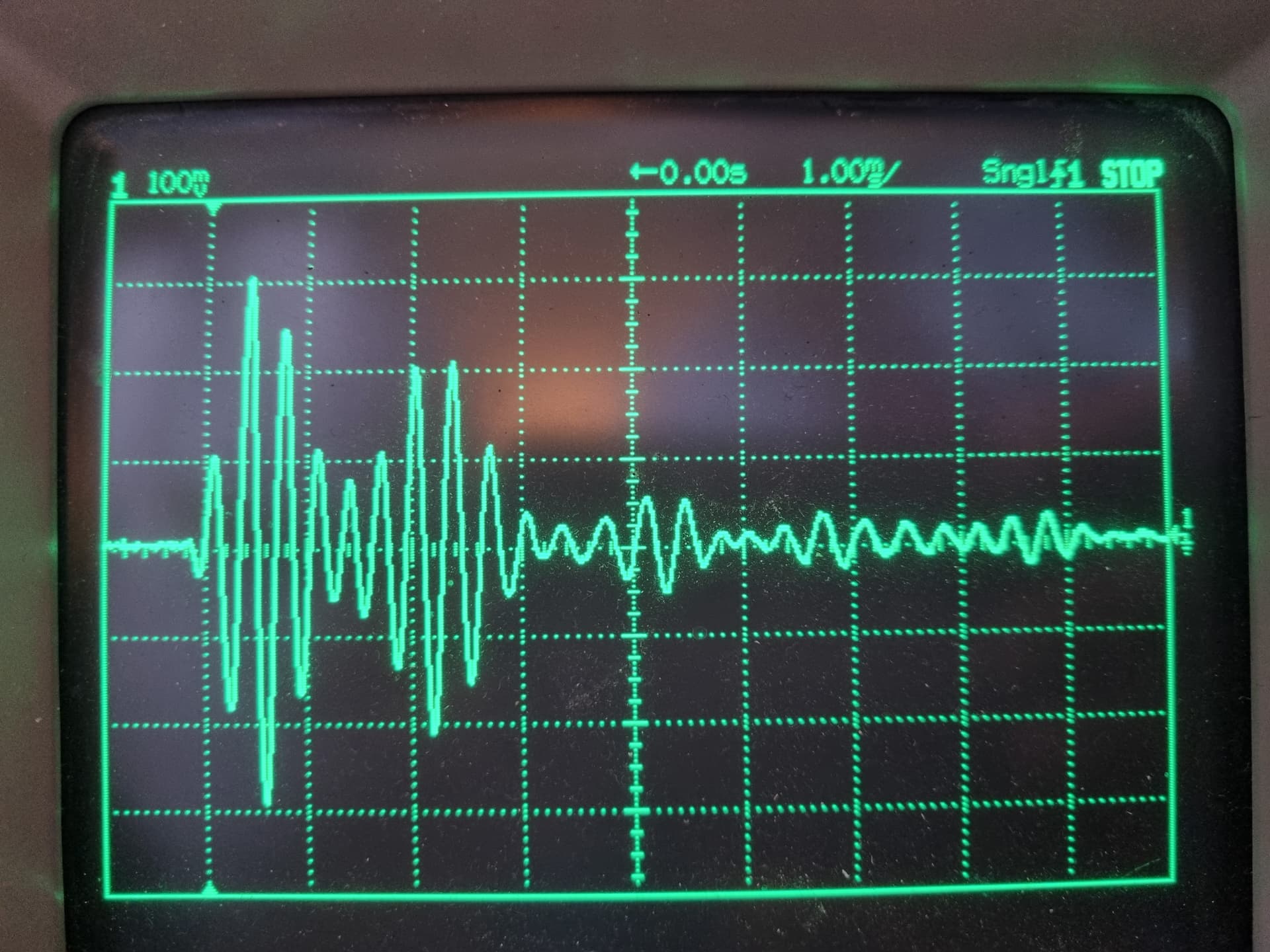
The good news is that the signal is clear and the reflection at the top is strong. The not so good news is that we are dealing with a large overlap between the signal and the echo. In the image, the reflected wave is added to the signal after a few periods, in this case causing a phase shift. The shift is consistent and clearly varies smoothly with the position of the tapping, but it’s a less clear-cut signal processing problem that what I had hoped for.
I will be doing some more rigorous experiments with a polycarbonate tube when I find more time to play.
Data from light taps made with a plastic screwdriver handle on a full thick-walled, milky white Neopixel-style blade (although home made with the more recent WS2813 LED strips), with a foam diffuser and a thin PE diffusing tube around two rugged IP65 silicone-sealed strips taped back to back.
The piezo sensor was taped to the outside of the tube right at the base. Having the sensor inside would work just as well and work without modifications to the hilt.
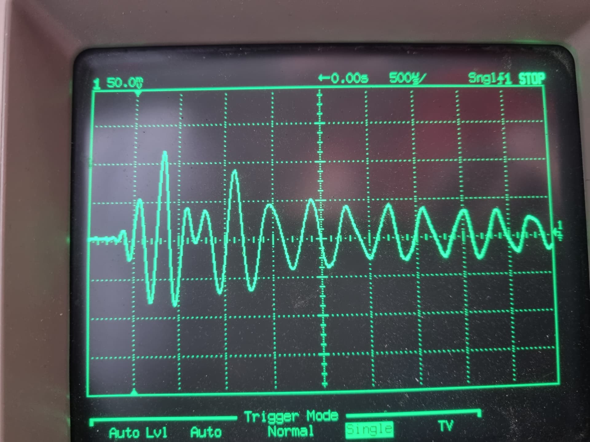
The thick PC tube had a higher natural ripple frequency for the Lamb-like shear wave along the surface and made the tap and its echo easier to separate.
From top to bottom, the traces are from taps at the base, 1/4 way up, half way up, 3/4 up and at the tip. Taps 3/4 up and higher might be difficult to distinguish from taps at the tip, but the other first echoes are reasonably clear even from a casual visual inspection and should be possible to detect automatically with good accuracy.
Thin walled blades would have slower oscillations and make the signals overlap more. (I have no thin walled blade available to me.)
I found an acrylic tube with thin walls of about the same dimensions as the 1" thin walled PC blades. PC and acrylic are quite similar in acoustic properties.
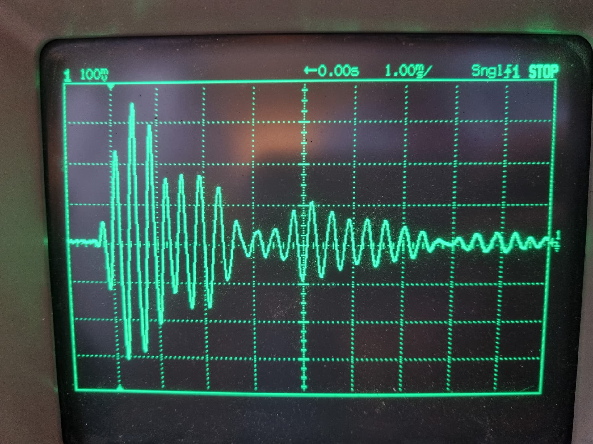
Using the same setup as for the thick blade above, no obviously useful data could be captured. The wave propagation is weaker, the ripples are slower which makes the echo overlap more with the direct signal, and the reflected echo is not nearly as strong as for the thick tube.
Fortunately, the thick walled blades are our main target, because that’s what people use for dueling. Right? For now, I won’t pursue the thin wall track further. I wouldn’t rule it out as a dead end just yet, but it’s definitely a more difficult problem to solve.
Unfortunately, I think the majority of neopixel blades are thin-walled, and even if you can’t duel with them, you can clash them fairly vigorously with no harm to the blade.
Thin-walled tubes leaves more space for the neopixels and the diffusion required to get it to look smooth.
Wouldn’t the vibrations in the direction of the blade be much much much faster, possibly leading to better detection?
The clash impact is an impulse in the radial direction, which excites a predominantly transversal “wavelet” (wiggle) in the tube wall. I think this is the signal we need to use. There’s bound to be some kind of high frequency wave in the longitudinal direction as well, but from what I can tell it’s too weak to be detectable with the budget sensor. A real ultrasound transducer might be able to pick it up, but it would be heavily masked by the transversal wave and difficult to separate. We would be listening for a weak “ping” in the middle of a loud “whack”. The waves propagate at different speeds, but it’s still a problem that one is so much stronger than the other.
My custom thick wall WS2813 blade is well diffused, but it took a foam sleeve, a diffuser tube and a milky white PC blade to get it smoothed out, and it was a very tight fit indeed to get it all in. I can see why people prefer to have some margins.
I’ll make another attempt at getting useful data from a thin wall tube. I might even purchase a premade thin Neopixel blade just for this. It’s not about the money, really, it’s just that the sources I have found for purchase take weeks to deliver to Sweden.
Meanwhile, I will try to make a visual clash demo for my thick blade, for inspiration. I have a first version of the detection algorithm worked out in Matlab, but I need to wait for that I2S input board to collect more data and make the detection more robust. Exporting data from my old salvaged HP oscilloscope is a painful process involving a 3.5" diskette…
My quick and dirty first algorithm has two steps: find the envelope by a lowpass filter, and if there are two envelope maxima within 4 ms, compute the autocorrelation in a narrow window around the time difference between them to refine the estimate of the offset between the signal and the echo. If there aren’t two distinct envelope maxima because the time difference is too small, run the autocorrelation with a wider search window from 0 to 0.5 ms and pick the maximum.
Note that this algorithm was tested on a total of four signals, because data export from my oscilloscope is a hassle. It might break badly in practice.
Yesterday, I did more experiments with the thin wall tube, and I must conclude that physics is working against us here.
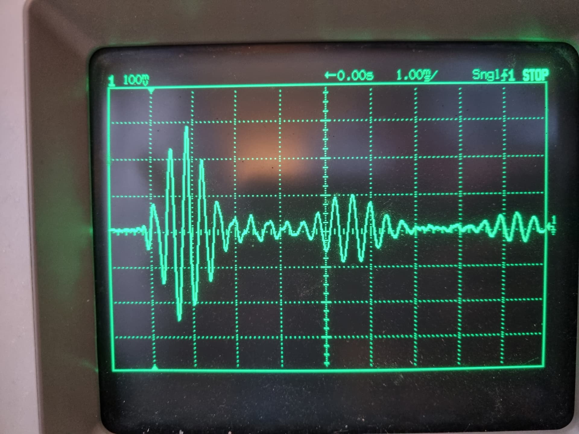
The thin wall tube is flimsy in comparison, and that allows for several wave modes on the cylinder surface in response to an impact. These waves travel at the same speed, more or less, but they take different paths on the surface. The cross section of the thin tube deforms more easily to an ellipse, which throws considerable energy into weird higher order bend-deformation waves that can be regarded as linear waves travelling in sort of double helix paths, taking one or more turns around the tube while also travelling in the lengthwise direction. These waves travel more slowly along the tube, which causes interference and makes the signal change its shape and phase during propagation, to the point where you can’t reasonably figure out what is happening using only one sensor.
Further adding to the woes is the fact that the reflection at the free end is weak for the thin tubes. Part of the reason for this could simply be its lower mass and therefore lower energy overall, but I also suspect that the waves that are not pure bend waves are more prone to energy losses both during propagation and in the reflection.
A surefire way of locating the impact point is to put one sensor at either end of the tube and just detect the first incoming wavefront. However, using only one sensor at the base, I see no way of solving this.
The thick tube, on the other hand, is sturdy enough to discourage all the weird mixed-mode waves and put most of the impact energy into a clean bend wave.
Disclaimer: I tested this not with a full thin-wall blade, but with an empty tube. Adding the damping stuff inside might alter the wave propagation properties in a favorable fashion.
Sensors in the tube might be a good way to go, but comes with some complications.
for the tip sensor, we’d need a way to mount it that doesn’t cause a lot of shading on the blade. Maybe we can sandwich is between the two neopixel strips? Does the sensor have to touch the blade to be effective?
If the sensor(s) live in the blade, either the sensor output, or the final result of the analysis will need to be sent back to the proffieboard in the hilt somehow.
One possibility would be to have the neopixel data go through a small cpu inside the blade. We could set up a 1Mbaud half-duplex serial connection with some simple protocol that alternates the direction after each packet of data. That way we could send neopixel data to the blade in one direction and clash information in the other direction.
Unfortunately, Proffieboards don’t have any pins that are capable of such a protocol AND also doing blade ID (analogRead) But it would be possible to do by connecting several pins together. (Data1, RX & TX)
I think sandwiching a piezo sensor between the two LED strips at the blade tip would work, and then the same mounting would be used at the base. With two sensors, all we need is a ramp detection and a microsecond-accurate measure of the time difference.
Transparent piezo sensors do exist, but they might not be needed.
For the simple two-sensor processing, an ATtiny or similar would do the job, and the data could perhaps be beamed to the hilt over a simple IR link? The blade is translucent, and IR LEDs and photodiodes are dirt cheap.
IR might work. It’s a little fiddly to make it reliable though. There are common IR receiver modules that de-module the 38kHz signal used in regular remotes. That sort of double-modulation is often needed with IR to get a reliable signal across, but they tend to be a big big for stuffing inside a saber.
Other options would be to overlay a high-frequency signal on the + or -. Just need some capacitors to de-couple from the DC component. Will still need the same kind of de-modulation that IR does though.
That 38 kHz standard is a severe limit on IR performance, but it sure is convenient to buy receivers off the shelf, and it might be fast enough for sending the few bits we need here. Some kind of HF sideband is a more attractive idea, I think.