Enter the Numchuck

Yes, I know they are called nunchaku (did you you the u is a swallowed vowel, so that in Okinawan it’s silent?).

First a disclaimer: I am a resident of NY state, USA, where nunchaku were illegal for quite some time. More info here on what changed and why this project is now possible. The laughing monk in this piece was my coach for about a year.

So if you decide to connect two sticks with a string, it’s on you to break neither the law nor your front teeth.

The idea for proffie chucks is certainly not new. It would have been a good fit for the hybernating M2, as pointed out by Profezzorn a while back. And I ofcourse considered other solutions, like the very cool PixelBlaze PICO V3. But proffie still reigns supreme with overall form factor and OS, even without dotstar/pov capabilities.

There are ofcourse light saber nunchaku on the market, but I don’t like their design pattern even if they are very in universe. They usually have two small hilts connected by a chain, with the blades pointing away and down. Shout out to Jedi Shaggy. We’ll leave the flow toys out…they are cool but are all blade. That’s not very Star Warsy.

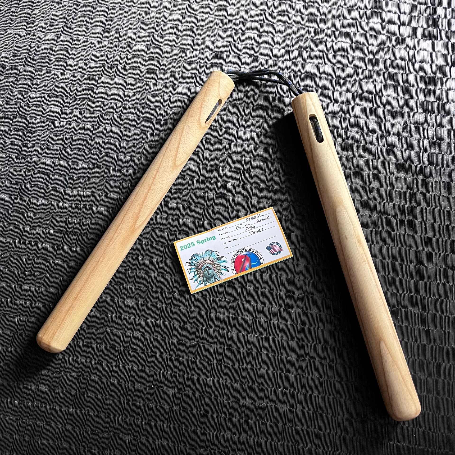
So in order to understand what I wanted, I bought cylindrical nunchaku from USA Nunchaku to try and figure out how they are used. Traditonal sticks are octagonal, but saber blades are round.

The summary is that if you grip near the top, you are doing art, and if you grip low, you’re doing martial. I practiced most mornings for about 2 months, and now they’re part of my regular training. Recommend! Great upper body workout, and very fun. This company makes very high quality tools.

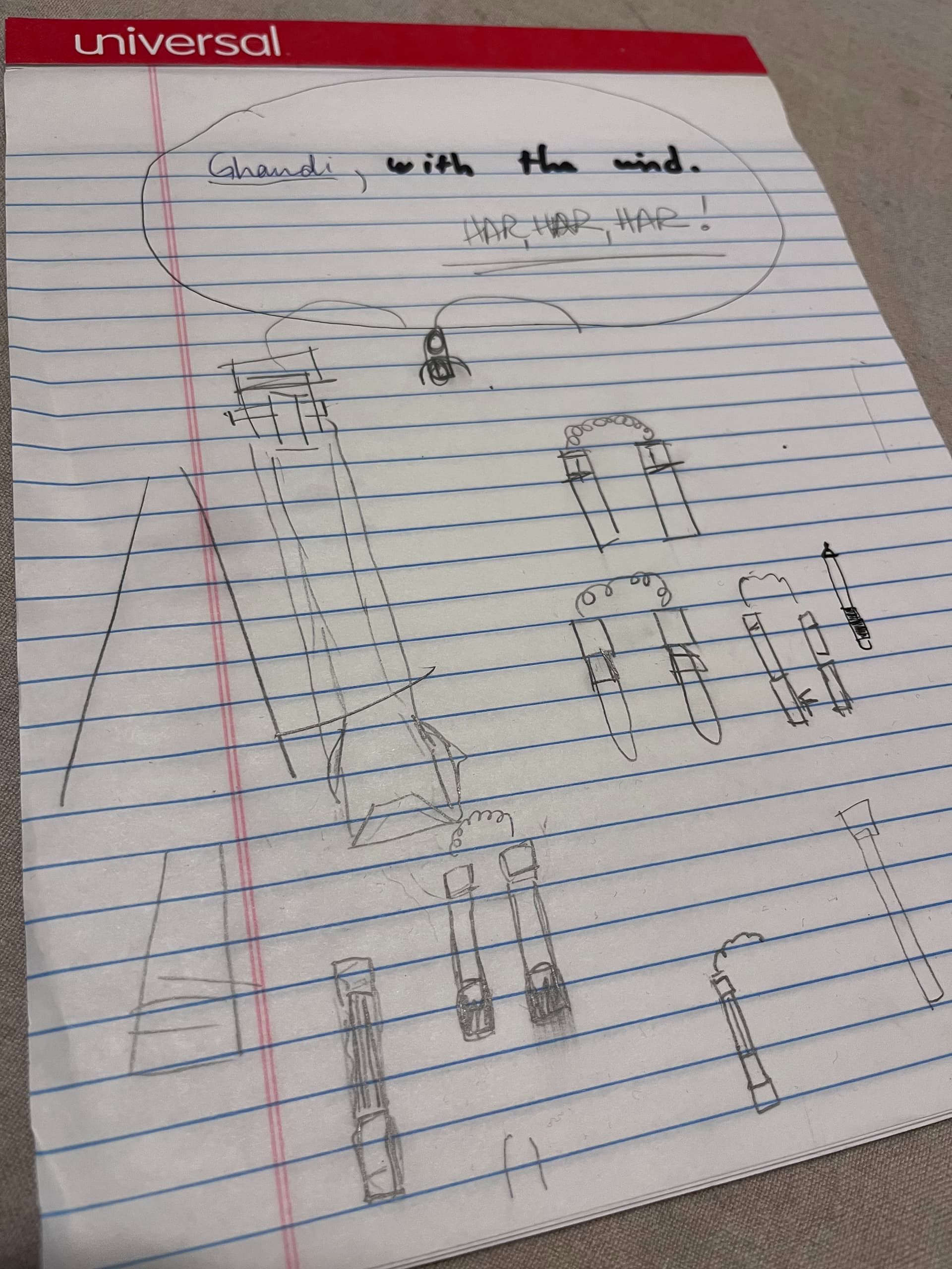
At the dinner (read: drinking) table my wife and I mulled over some designs:

There are some real issues with making these things, mainly that I wanted a low grip to keep it martial. A low grip means a killer amount of centrifugal force. Here are the chucks I received. There are three lines of paracord connected them, embedded in the wood. I choose “jedi” as the cord color, ofcourse.

So my big fear is a chuck flying away, or swing stress pulling on the components. They need to be very, very secure.

This means no wiring btw the blades. Too stressfull, literally. So this project requires two proffies, IMO. The wooden (ash) sticks are extremely light, but get VERY heavy when you swing like you mean it, which meant an 18650 in each stick would be a death wish. Also, the top of the blades near the cord would have to be much stronger than I anticipated.

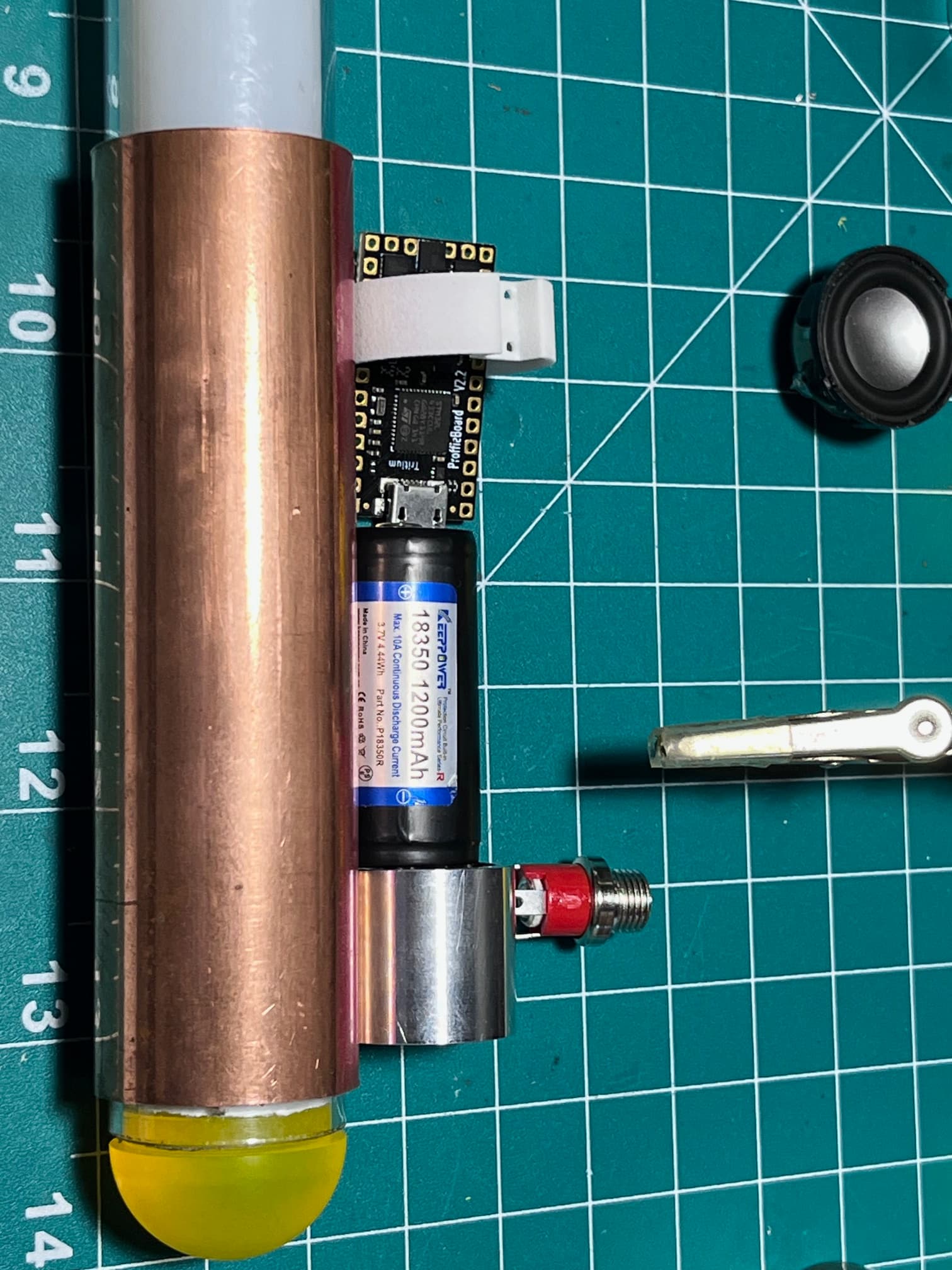
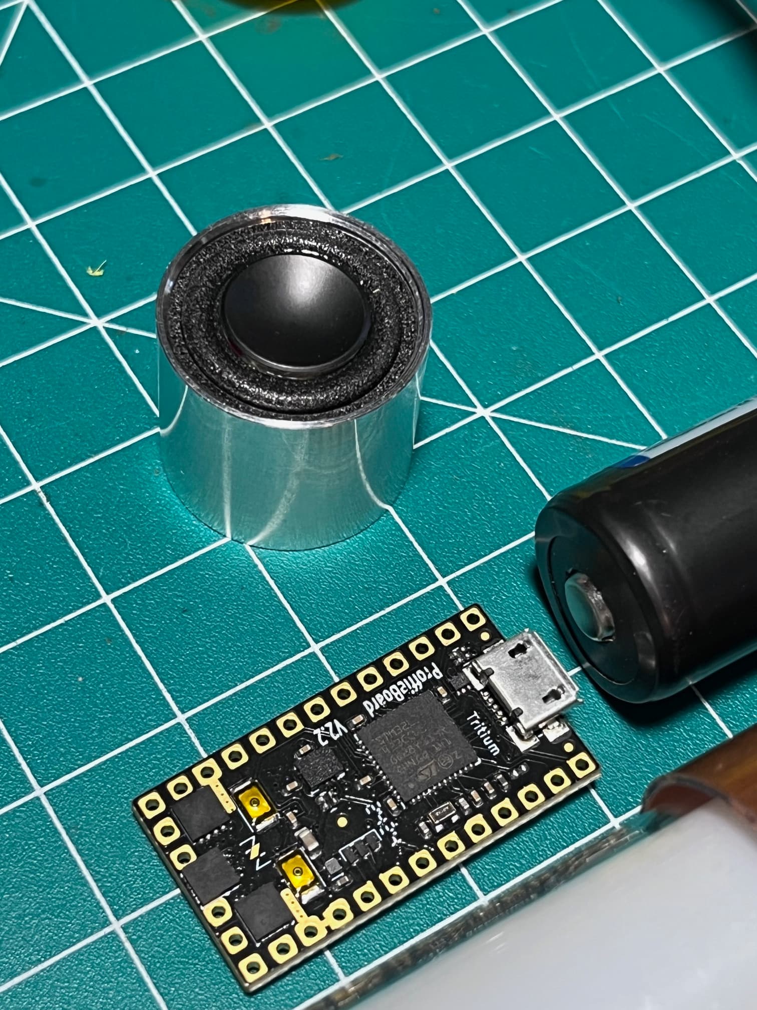
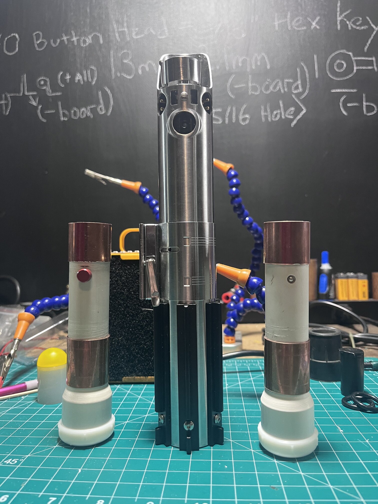
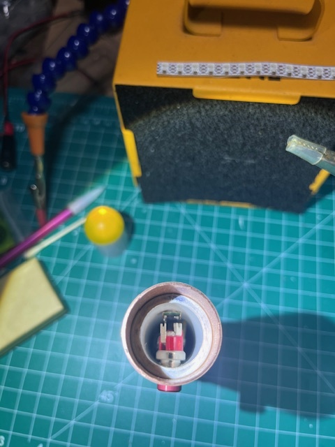
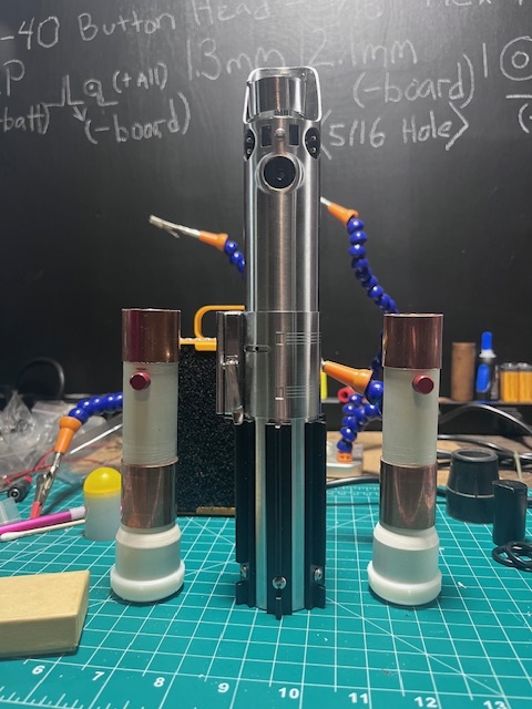
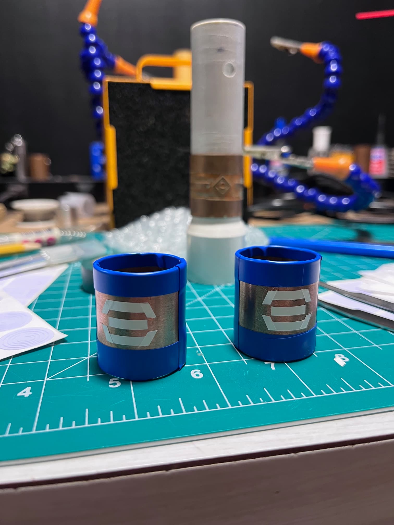
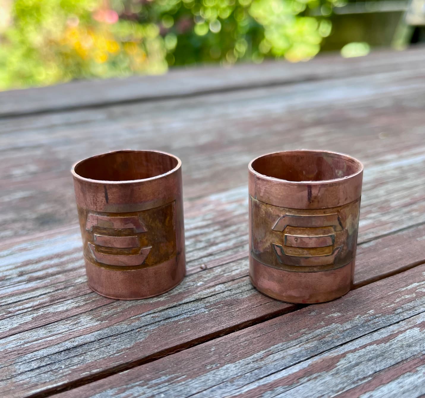
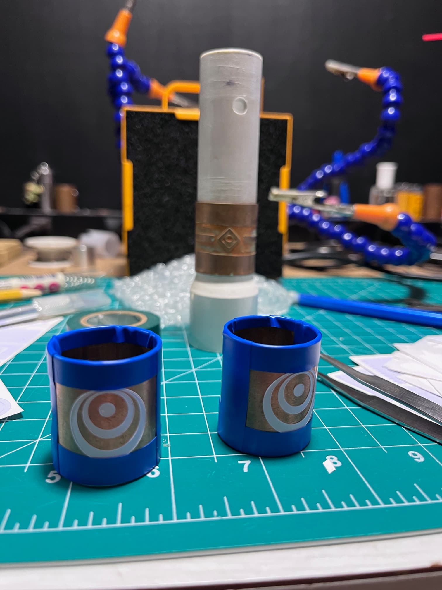
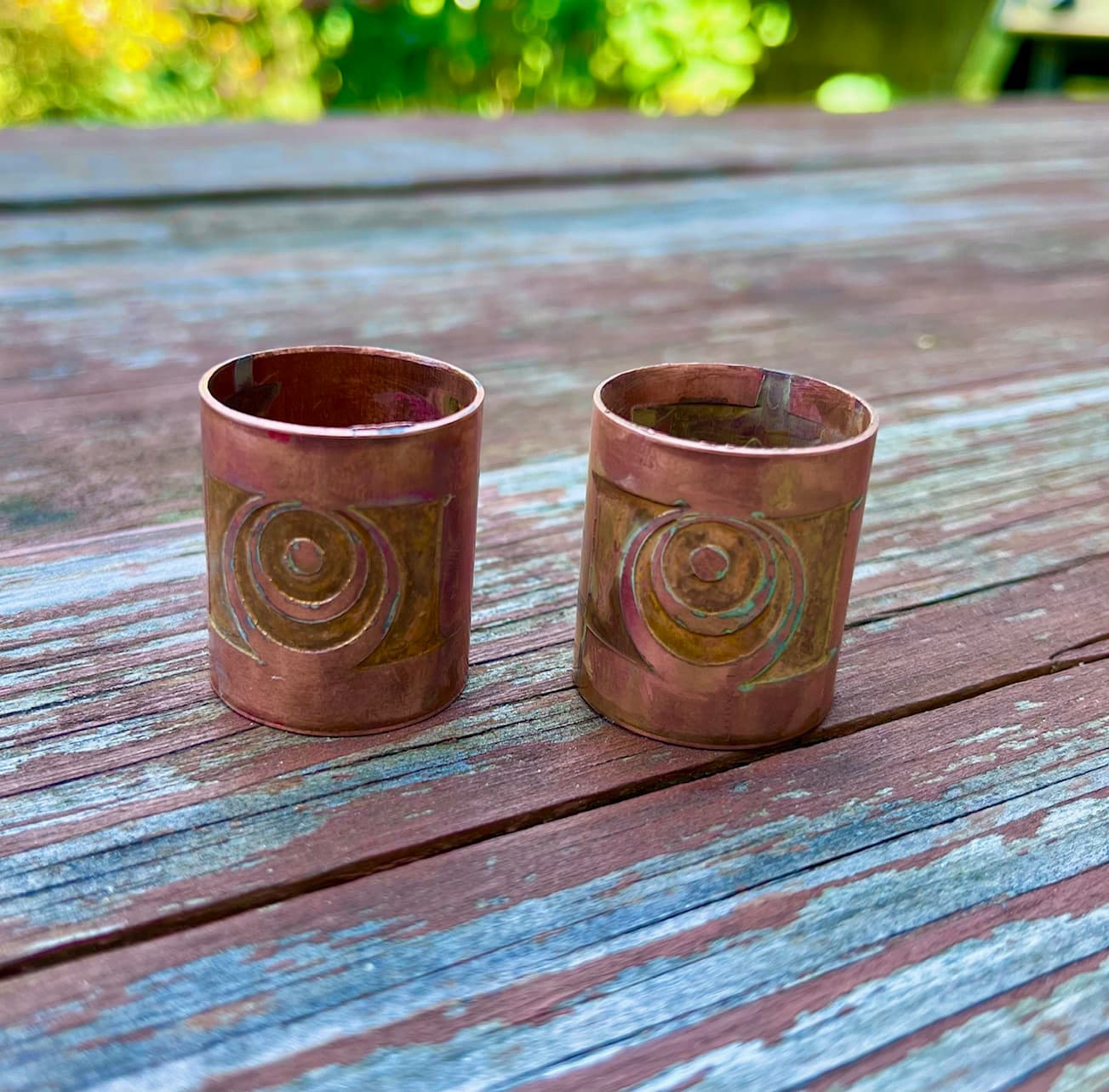
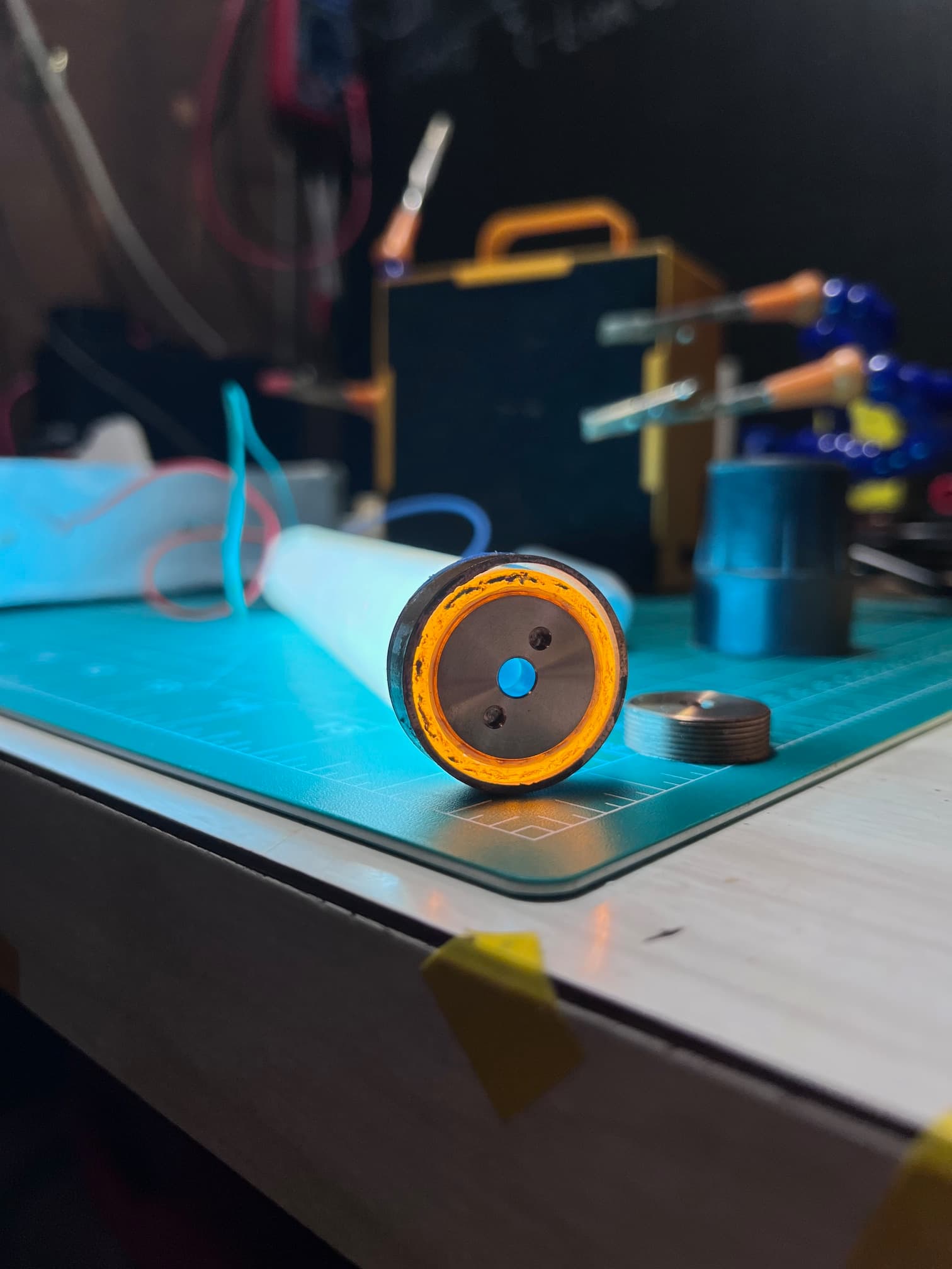
After several frustrating attempts at a top deisgn, including using all kids of bearings and caps (fishing bearings came close), I realized a 7/8 tri-cree heatsink under a pcb holder could give me the look and stability needed.
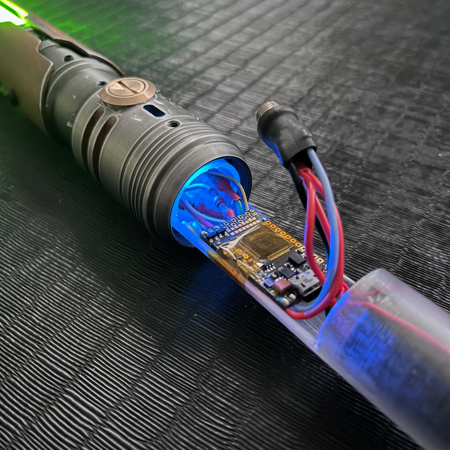
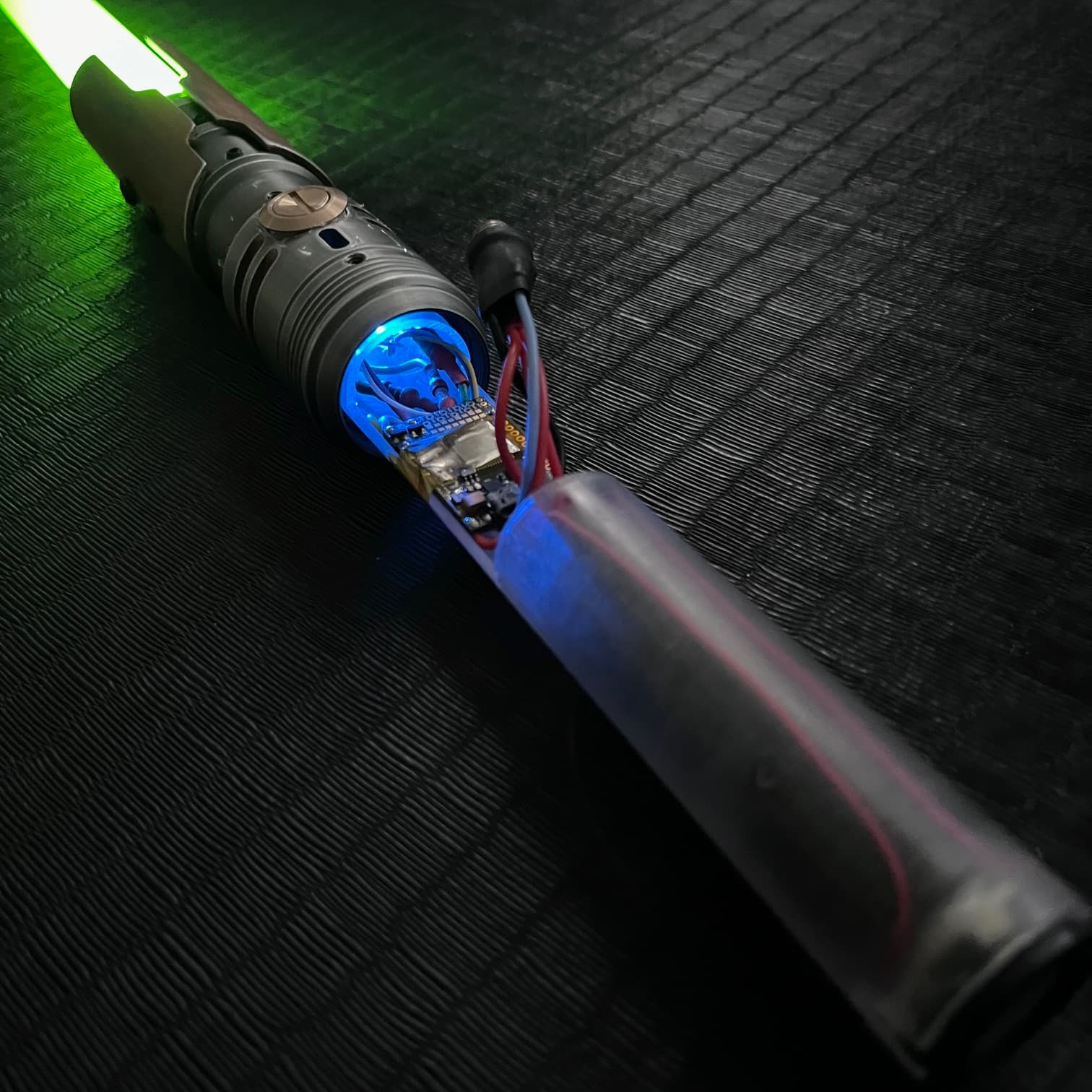
Like so:

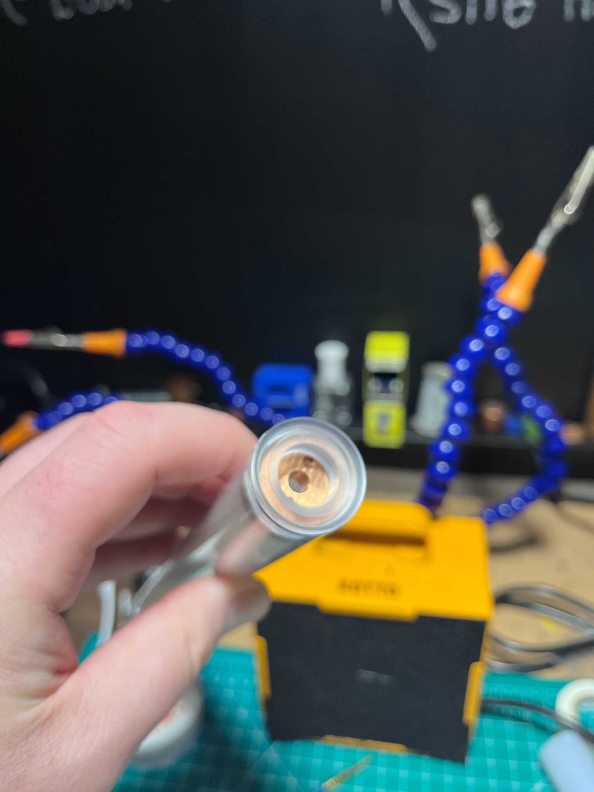
Only testing will tell though. The triple paracord loop also showed me that bearings are not really needed. You can whip figure 8s and there’s not real loss of motion from the rope being stable where it hits the stick.

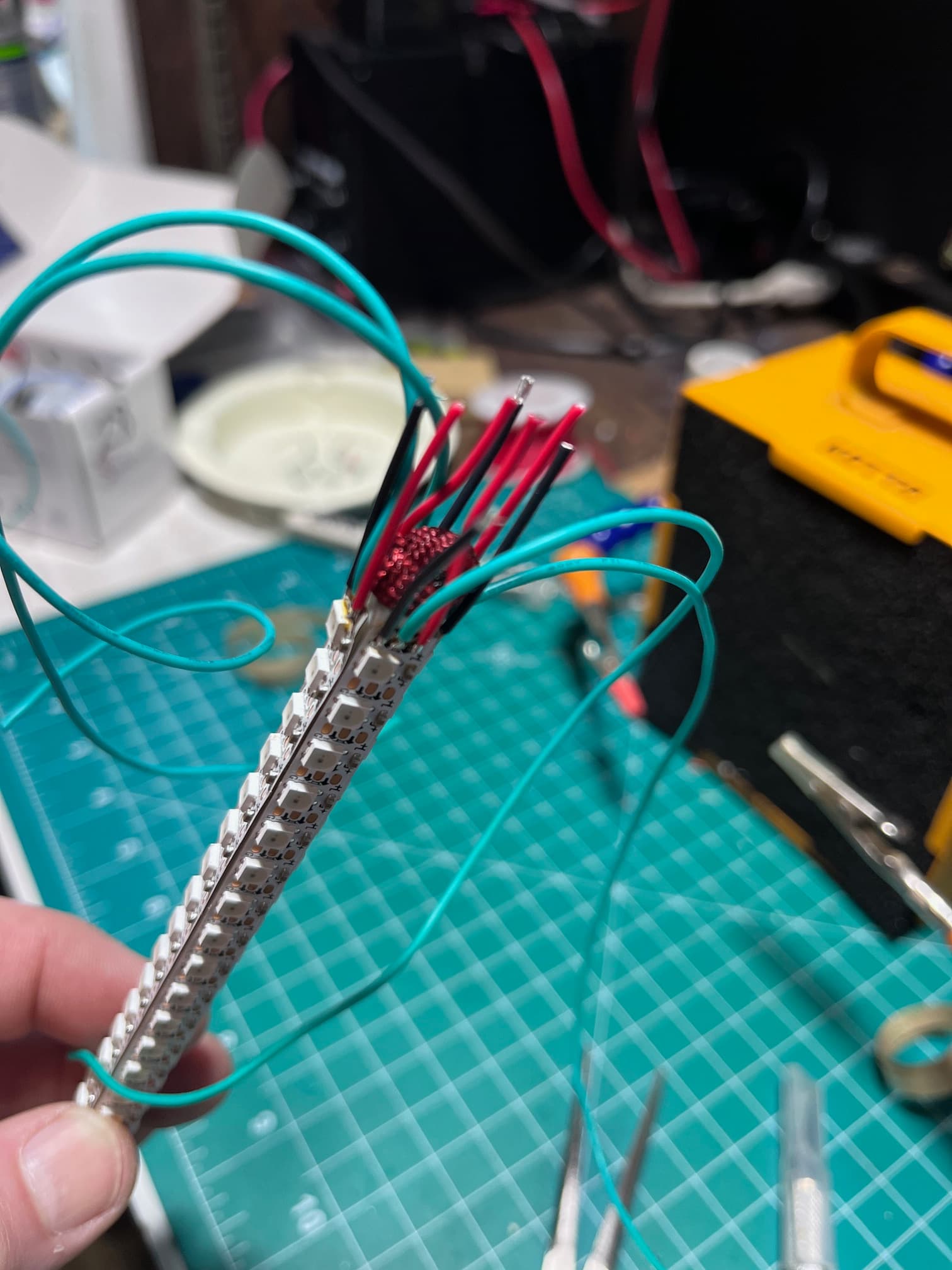
So to conclude this intro to the build, I’m ready to set up the basic blades and have found some other solutions that I’ll share. If I was making these for the screen, I’d make empty beskar casings that could be used as a blunt weapon with the kyber blade inside for blocking. Then you could pull of the case and start chopping up the Knights of Ren with the bare blade. But in reality, I want the thinnest, lightest chucks I can make, with a compromise between Star Wars in universe blades and the infinite blade of flow sticks.

And a final fun fact from my research: many of Bruce Lee’s famous moves are not possible with regular nunchaku, particularly his armpit stall. He modified his screen chucks so that the chain was the same length as the sticks…12 links instead of the 3 or 4 you’d find for martial arts practice. Clever.

More soon as summer project season approaches! Thank you for checking out my build log!

I’ve also thought a fair amount about how to make chucks. I’ve kind of thought that you might need to just drill a hole in the tube and put a nut-and-bolt through it to keep everything secure.

Also, I imagine that you can put wires inside the paracord. If not, there are lots of rope/string that have a hollow center which can accommodate a wire or two.

If you really want to build something durable, you might want to fill the tube with liquid epoxy, or clear resin after wiring everything up, but after that you cannot repair anything if it breaks…

The nut and bolt idea is good, and I considered running the bolt through the eye of one of those fishing swivels and having it poke through the cap.

Resin gets bubbly…I would forever obsess over the little bubbles I couldn’t get out :slight_smile:

I’m doing little hollow quad blades (I can’t help it, love them) and may run the attaching cord all the way through to hold on to as much of the blade as possible. I could put some resin in there and lock in the cord! Hmmmmm…

I believe you make the bubbles disappear if you use a vacuum chamber. No personal experience but seen many times on Youtube.

Yeah me too. I really like The Crafsman’s videos about toy making and resin casting.

They don’t really need to resist heavy impact. It’s the math of the acceleration creating the pull between the sticks. I’ll take a video of what I mean when I can. It was shocking to me how much, ahem, force is involved. It’s far greater than the pull of a blade out of a hilt, at least subjectively.

Sounds really awesome! keep us updated

1 Like

How about this:

  1. Get a silicon tube that is almost as big as the inner diameter of the blade.
  2. Thread the silicone tube through the hilt
  3. Stretch the tube to reduce the diameter.
  4. Insert pixels around the silicone tube
  5. Stop stretching silicone tube

The silicone tube increases dimension when it swells and holds everything in place… Should be fairly flexible and durable.

Oh, I forgot a step: The silicone tube will need to be cut, so getting it out would bard, and getting back in again is probably impossible…

1 Like

Decisions that are settled:

1 - There needs to be a 4" copper grip min which will conceal the electronics. It’ll be acid etched (not sure what pattern). That’s about the width of my grip and any excess covering of the blade is a dash of fail.

2 - Although I usually don’t prototype, there is so much risk of damage just from swinging that physical stress testing is in order. Each piece will be built with scrap blade tube before the final, and it will have to swing well empty + the battery cells.

Uh…yeah not sure about the rest but I tried 2 layouts so far.

Layout 1:

Here the end piece below the grip would be primary access. There’s a 4ohm 3watt 20mm speaker inside the upper housing that accompanies the heatsink that will be used to house the connecting cord/chain.

Like this:

The proffie would sit centered in a switch ring (from TCSS). There’s not a lot of blade depth, which is not good and may not endure the swing stress. BUT, I can do a “blade chassis” and have the copper piece acting mostly as a shield. That messes up the switch and I’d have to put it on a spring, so I could compress it and remove the copper to get acess to the internals. The recharge port would live inside there some where. Not sure.

I did a similar set up for my brother in law. I was specifically instructed by my nephew to make him a saber “not as cool as mine”, so it’s a baselit CFX :stuck_out_tongue_winking_eye: in a Flyte hilt that I painted and weathered for a Boba Fett look. The blade is an early photonic green dueling blade I repurposed. This gives the shine through one color, and the blade another from the same tri-cree:

But, I dunno. As Moe Howard would say, it’s my idea but I don’t think much of it.

So here’s layout 2:

This doesn’t have the passthrough blade chassis, which increases the internal diameter. I can stack the battery and the board and use an external recharge port, and a 24 mm speaker. The rcp can sit opposite the single tac switch, which is part of the tail end of the chuck. They can be fixed because I get a 1 inch blade depth back and can open the core from the top: There will be 4-40 button head “rivets” that go into the blade tube itself, which could be removed for access to the internals. No set screws that use pressure.

Here’s how I did the switch ring in the lower blade:

It’s on the outside for a near perfect fit to th ID of the copper. It’ll need a little sanding once they’re bonded to get it just so.

I’m using enchaced amber blade tubes to summon the golden dragon vibe, so that’s why the blade tips look like that.

Next I’ll figure of these two build styles to try as a full swingin’ prototype. These are quite dangerous compared to the usual saber chucks with the heavy hilt at the top. Not for the kids.

Feedback welcome, and thanks for looking!

1 Like

Working on the top section, I am wondering if I can get away with a simple knot through the heat sink. I’m not too familiar with paracord. I got to see how much length you lose in knotting and how it melts when you clean up the ends with a lighter. Strong, but I need to compare the physics of this vs feeding the cord through the center of the blade.

This is a full 12" Bruce Lee 1:1:1 length cord.

Did a test with scrap blade for the swing feel, using metal grips, the batteries, and the heatsinks at the top. At 12” x 12” x 12” they were literally deadly. So I tied them off at 4” as the center and they became manageable. If they are shorter than arm’s length you can always starighten out your arm quickly and avoid hitting your head.

Wife’s feedback: “maybe the reason nobody does this is because it’s hard, dangerous, or looks dumb”

Next test will be to run the cord through the center of the whole blade. This would place the heatsinks at the bottom of the blades, and they could be used as anchor points for the grip/hilt.

Also trying out speaker placement. In this case it would be like a typical saber, but only 20mm. But these look like candles to me more than nunchaku so I might hide the speaker deeper in the grip and go to round tips on both sides, with the center drilled out for either sound or the cord.

Also going to try pvc grips with metal joints.

2 Likes

Ok, I have couple new solutions.

The metal grips look good but are not realistic for use. It’s about a dangerous as a metal tipped rope dart or meteor hammer. Mine is a tennis ball on a string :slight_smile:

Here’s a mock up of one of the grips I’m gonna use. In the base will go a 24ish mm speaker, and then there’s room for the sound to resonate and for more LEDS to loop around. The board will be accessed by removing set screws in the base, with the pommel lights and speaker all removable as a unit.

ChuckHandleStart

The copper coupling at the top will be bonded and rivet screwed into the blade tube and the grip.

Lots of sanding and getting things cut to match and fit next. Then to build the internals of the blades.

I’ve been able to reduce the size of the install to the shortest length the parts allow for in a line, shaving another inch of the pvc (the section btw with copper is only 3").

Wired: More depth lower section to fit the battery above the speaker.
Tired: Extra LEDs in the speaker section (not happening).

Recharge port is directly opposite the single tac switch.

The battery sits just past the speaker and so on. Fixed blade will couple with the upper ring.

For size comparison, here are the hilts next to the graflex I’m installing.

And here’s a view down the pipe, with all parts seated but neither wired nor glued. I usually use silicone coated wire for no-chassis installs, so hopefully that will work.

NunchakuFit

Turns out one of the hardest things to do with just hand tools is symmetry! Doin’ my best:

NunchakuMatchingGraflex

Next is finishing work including cleaning, sanding, and reaming the switch holes for the pvc. The copper needs to be cleaned, marked with a resist pattern and etched.

Then I’ll build our favorite part: the blades :slight_smile:

2 Likes

Today was a classic “failure is always an option” kind of build day. In my other quad-blade builds, I always used a zig-zag blade design. However, my double bladed zig-zag staff couldn’t take advantage of the new “maul ignition” and I became discouraged. Moving forward I though it might be better to just do a normal strips in parallel set up. This was a mistake :upside_down_face:

Since there’s no pcb at the hilt/blade transition, my idea was to use harder (PTFE) 22awg wires at the base of the blade for stability on the power lines, then run silicone wire down into the hilt. Unfortunately this turned out to be a mess. Hiding the lighter welded knot in the paracord at the base of the blade did work, but the path of the wires around the slightly larger knot became an issue quickly with so many wires:

I had trimmed the pads off of the top pixels to maximize the reach of the light up the candle sticks, and lost one pixel off of each prepping them to be zig-zags:

My real mistake was I hadn’t considered the value of the proximity of the ground and pow+ when zig-zagging. Of course, the advantage of a reduction of 4 to 1 data wires coming off of the blade was obvious. But having the ground and pow+ lines next to each other at the blade base is a HUGE advantage. Now ground will be on one side of the knot, and pow+ is on the other, and we will have peace. I hope.

Acid etch.

Masked:

About 90 min in the acid, then “quenched” in baking powder solution, and weathered by leaving to bake in the sun then get rained on:

My wife says they look “Star Warsy”. Satisfied.

2 Likes

Looks awesome! I’m excited to see how they turn out when finished.

1 Like

Some quad zig zag blade tests.

Naked:

Complete-ish:

2 Likes

Looks great! Do you see any shadowing with the quad blades?

1 Like

Thank you!!

For context, the least amount of shadowing I’ve been able to get in any blade is with a KR stick direct soldered to a pcb. I can’t find the center seam even when I look for it.

Here pixels are smaller, dimmer, and a bit more spaced out than on a standard 144 pixel/meter strip.

To compensate, I’m using an enhanced blade (Amber) that has its own glow, heat shrink around the led bar, and then foam and hard diffuser tube. It looks perfect in motion, but is just shy of what had become the standard (or I guess pro-tier).

So it’s about as good as a well diffused standard neopixel strip you’d duel with, but not as good as a ‘show blade’.

I was able to present my progress to my wife and a buddy of mine because I was secretly hoping some of the shortcuts I’d picked looked cool enough. But when they saw my original and much harder plan…I’m gonna need a couple parts and a lot of hours. And some leather. And brass pins….:smiley:

Acid etched the couplings for the blade to attach to the grips. The loops are supposed to envoke some of the jedi symbology, and the aurebesh letter on the back is a “B”, because at work I’m “Mr. B.” That part was hard. As you can see I made it by hand cutting salon stickers and nudging them into place. Then shaped them with an exacto. 90 min acid bath.


Also I’m looking at leather for weaving into the cord btw the batons. The paracord was cool but in asking for feed back “why aren’t you using leather” was a popular question. I want to get to a cylinder with maybe 3 or 4 thin bands woven together. Anyone have any tips or suggestions?
The baton tops are capped like this:

They need finishing work, like sanding. The loose outer ring will be cut and welded to size (with a plumber’s torch and solder). The middle part is a 7/8 heatsink for baselit sabers. A 4-40 button head screw (maybe 3?) will pass btw the inner and out copper, changing the shadowing. I want a strong bond there and don’t want to weaken the tubing with to many screws, or ruin the look with too much adhesive.

2 Likes