Eco Hero Master Wiring Question

Hi all,

First time builder, and while I have had some experience with soldering, this is by far the most complicated electronics that I have worked on. Using the config generator and the provided wiring diagram I have created this wiring diagram, and was hoping for feedback on it. I also have my draft config that I would be incredibly grateful to get looked over. Equally, if I’ve missed any forum guidelines, please feel free to correct me!

myconfig.h (25.5 KB)

Do you have some documentation in the switch led board?
Without that it’s hard to know if it’s right or wrong.

No documentation I’m afraid, but here’s a photo. Khal at KR has told me it should just wire up like regular switches and accent LEDs. Here’s a photo of the contacts on the board if that helps


It’s got Switch 1, common, switch 2, red+ red-, green+, and green-

Hard to read, but looks like two switches and two plain LEDs.
Does the led board have resistors for the LEDs?

It does, yes

So I think you want to hook up Free1 / Free2 the other way around.
(Free1 ↔ LED+ , LED- ↔ GND)

The way you have it will work, but it will be dark at 255 and bright at zero.

Brilliant, tha k you so much, you’ve saved me no end of troubleshooting when I try and get my config to work!!

I’ve wired it all up, using the following diagram and config, but blades 4, 6, and 7: The accent strip and PCB LEDs are not working at all. I can’t tell if it’s an issue with my config or possibly the wiring?

am no expert so hopfully one stops by :slight_smile: and have only built the eco chassis so far(my master chassis is on order)

only mistake i can see is i don’t think the accent led’s are cree based(again no expert), this is what i use for them
SimpleBladePtr<CH2LED,NoLED, NoLED, NoLED,bladePowerPin4, -1,-1,-1>(),
SimpleBladePtr<CH1LED,NoLED, NoLED, NoLED,bladePowerPin5, -1,-1,-1>(),

i also powered them from the 3.3v as per the wiring diagram on thesaberarmoury

Thanks so much, I’ll give it a rewire and see if we’ve got any more luck!

@Maff76 rewired, but still no luck. I’ve been tweaking the config to see if I can persuade it to work but also nothing. Would you be able to send me your config so that I can compare them and see if I can reverse-engineer mine?

Will upload in a couple hours once home :slight_smile:

here ya go, config - Pastebin.com again no expert but some how fumbled my way through it hehe

for my master build i was planning on adding the below and 2 more styles in each font
{ 0, WS281XBladePtr<112, bladePin, Color8::GRB, PowerPINS<bladePowerPin2, bladePowerPin3> >(),
WS281XBladePtr<1, blade2Pin, Color8::GRB, PowerPINS<bladePowerPin1> >(),
WS281XBladePtr<3, blade3Pin, Color8::GRB, PowerPINS<bladePowerPin6> >(),
SimpleBladePtr<CH2LED,NoLED, NoLED, NoLED,bladePowerPin4, -1,-1,-1>(),
SimpleBladePtr<CH1LED,NoLED, NoLED, NoLED,bladePowerPin5, -1,-1,-1>(),

Sorry to revive a dead thread, I’ve finally returned to the project. Wiring it as I had initially planned is the only way I have been able to get the accent LEDs to work. Therefore, is it possible - and if so how would I best go about - creating a style that’s essentially inverted, to trick the saber into being light when it thinks it’s dark and visa versa?

I don’t quite understand why you’ve used two LED pads (4 and 5) for one of the accent strips. If you just use one LED pad for that strip, that leaves two spare so you can then give the switch PCB LEDs an LED pad each which will make them much easier to control.

I’ll try it out! While the LEDs are wired in reverse at the moment, they are still being addressed, will switching to the other pads have a noticeable difference over using the free pads?

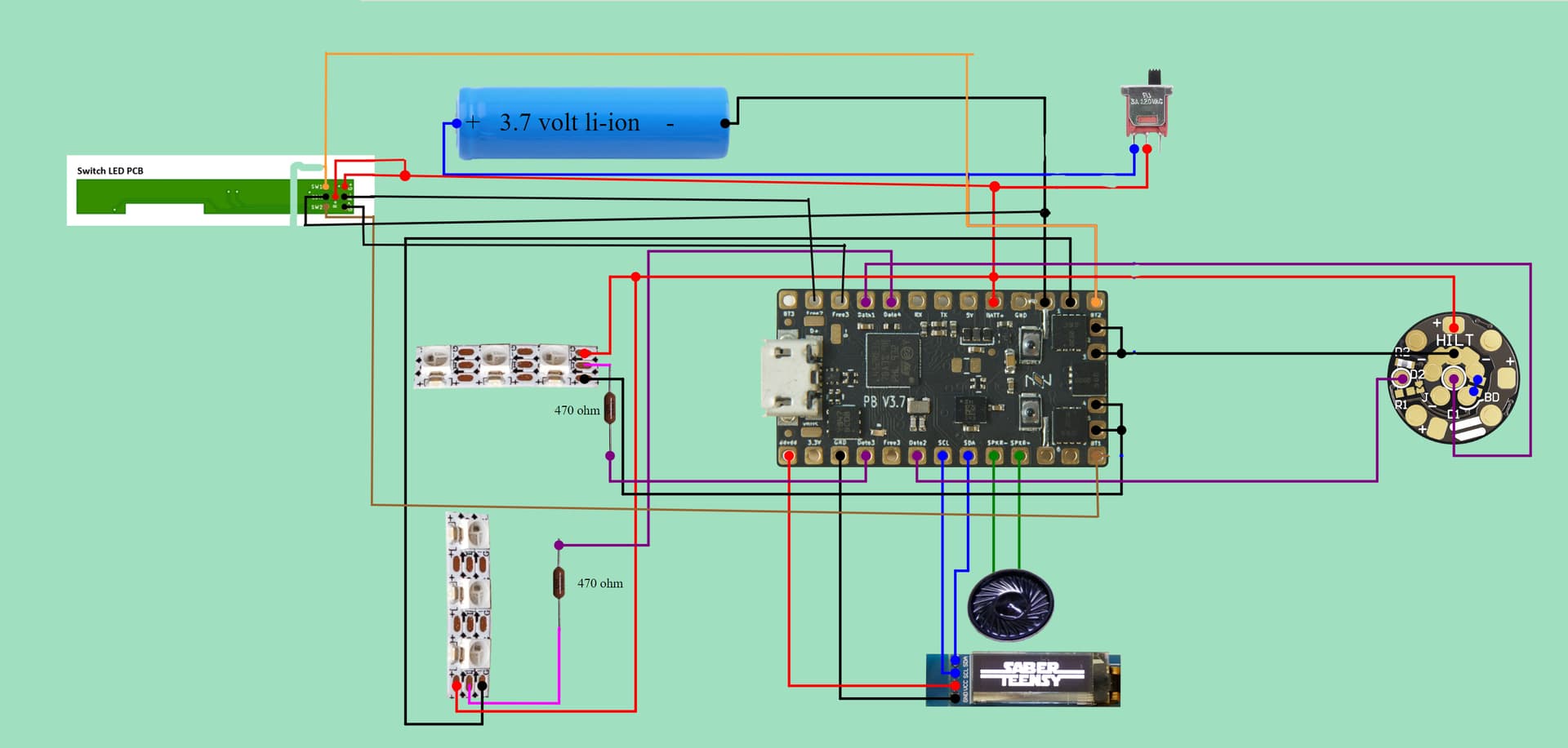
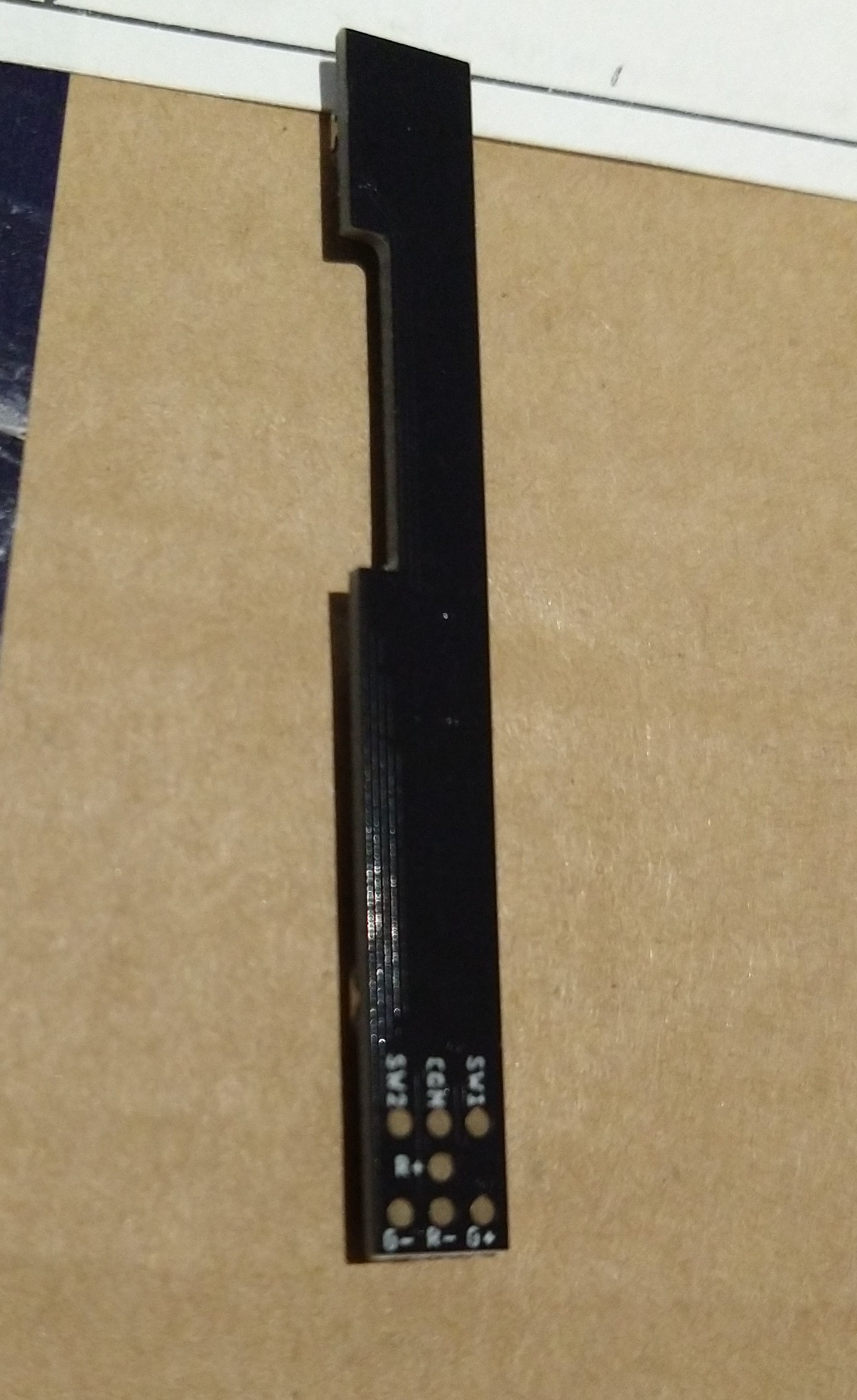
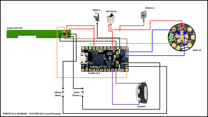
I must have missed a post somewhere along the line, as I’m not sure what you mean by them being “wired in reverse”. Normally you would simply wire the R+ and G+ to the battery positive or the 3.3 volt pad, and the R- and G- to an LED pad each. The LED pad provides the negative, but you need to specify it in the blade array in your config.

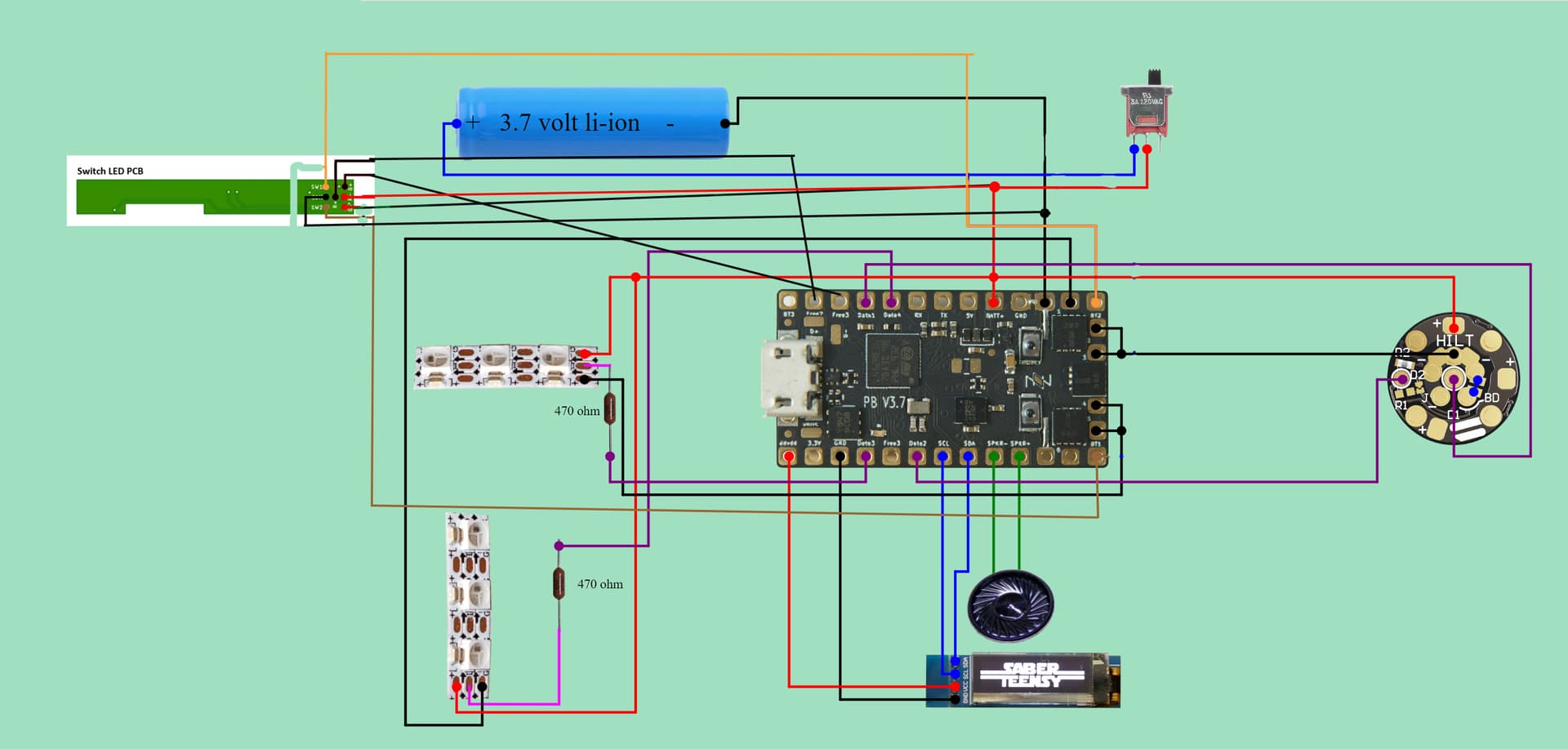
So the array for your diagram above, but changing the accent strip to one LED pad instead of two, and then wiring the switchbox LEDs to LED pads 5 and 6, might look something like this:

BladeConfig blades[] = {
  { 0,  
//  Main Blade:
 	WS281XBladePtr<132, bladePin, Color8::GRB, PowerPINS<bladePowerPin2, bladePowerPin3>>(),
//  Blade Connector LEDs:
 	WS281XBladePtr<6, blade2Pin, Color8::GRB, PowerPINS<bladePowerPin2, bladePowerPin3>>(),
//  Accent Strip 1:
 	WS281XBladePtr<3, blade4Pin, Color8::GRB, PowerPINS<bladePowerPin1>>(),
//  Accent Strip 2:
 	WS281XBladePtr<3, blade3Pin, Color8::GRB, PowerPINS<bladePowerPin4>>(),
//  Switchbox LED Red:
	SimpleBladePtr<CH1LED,NoLED, NoLED, NoLED,bladePowerPin5, -1,-1,-1>(),
//  Switchbox LED Green:
	SimpleBladePtr<CH2LED,NoLED, NoLED, NoLED,bladePowerPin6, -1,-1,-1>(),
   CONFIGARRAY(presets) },

Then your blade styles might look something like this:

//  Main Blade:
StylePtr<InOutHelper<SimpleClash<Lockup<Blast<Blue,White>,AudioFlicker<Blue,White>>,White>, 300, 800>>(),

//  Blade Connector LEDs:
StylePtr<InOutHelper<SimpleClash<Lockup<Blast<Blue,White>,AudioFlicker<Blue,White>>,White>, 300, 800>>(),

//  Accent Strip 1:
StylePtr<InOutHelper<ColorCycle<Blue,0,1,Blue,30,150,1500>,300,800,Blinking<Black,Blue,1800,500>>>(),

//  Accent Strip 2:
StylePtr<InOutHelper<ColorCycle<Blue,0,1,Blue,30,150,1500>,300,800,Blinking<Black,Blue,1800,500>>>(),

//  Switchbox LED Red:
StylePtr<InOutHelper<Blinking<Red,Black,1000,500>,300,800,Blinking<Red,Black,3000,500>>>(),

//  Switchbox LED Green:
StylePtr<InOutHelper<Blinking<Black,Green,1000,500>,300,800,Blinking<Black,Green,3000,500>>>(),

Hope that helps. :slight_smile:

1 Like

It should be possible to make this work with wiring.
However, it might also be possible to mess with the LED structs to make it invert the signal, I’ll take a look to see if it’s possible…

I finally got around to figure out how to invert the PWM signal so that you can hook up one of the Free* pins to the negative side of a LED if you like. To do that, you would add this before the blade array (or in CONFIG_STYLES) in your config file:

template<class LED>
struct InvertPWM : public LED {
  struct CustomColorSelector {
    static int Select(Color16 c) {
      return 65535 - LED::Select(c);
    }
  }
}

Then you would use it like this:

  SimpleBladePtr<InvertPWM<CH1LED>, NoLED, NoLED, NoLED, freePin3, -1, -1, -1>()

This will invert the drive logic, so the signal will be high 100% for black and low 100% for whatever color is is selected. (red in this case.) Note that if the positive side is hooked up to BATT+ then the led might never really turn off since BATT+ has a higher voltage than what the Free* pins can put out. (3.3v) Most LEDs will put out little or no light if the voltage is less than a volt, but I would still recommend powering the LED from 3.3v rather than BATT+.

So does that mean we could wire a plain 3mm LED with its positive to 3.3 volt and its neg to Free1 and then control it as a blade in the normal way, but just with colours inverted? So say we want the LED to be off when the main blade is off and then blink when the main blade is on, we could use this blade style:

StylePtr<InOutHelper<Blinking<Black,White,1000,500>,300,800,White>>(),

So this effectively gives us nine controllable LED pads! :smiley:

Which in turn raises the question, if we flip the wiring and wire LED neg to GND and LED positive to Free1, can we do the same thing but without needing to invert, or would that only work on non-neopixel installs? (In the same way that we can use data pads to control LEDs on baselit builds).