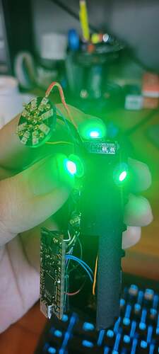
Morning all, I have stumped the mighty Fett263 on my facebook post regarding this issue, so he recommended I follow up here.
I am working on a build using data 1-4. However, nothing I do can get data 1 or 4 to work. 2 and 3 are fine (3 is the sub blade array of three pixels that can be seen working in the last photo, 2 is the data line for the blade, verified that it was working with a little test pixel), but 1-4 have nothing working at all, even after swapping boards. Data 1 worked on the first board previously, as I pulled the board from a previous build for an unrelated issue. This makes me think it is config related somewhere but I can’t seem to see it. I’m on OS6 if that matters.
Pastebin below, as well as photo of issue presenting itself. I have more photos of my wiring I can post, but it’s saying as a new member I can only add one photo. Hope I can add them as comments if need be. Anybody know what I’m missing? Hope I’ve given enough info, let me know if you need more.
I don’t see anything wrong with the config file.
I do however have a list of things for you to try to to see if we can figure out what’s going on here…
- Have you tried attaching the test pixel to data1/data4 ? Maybe the problem is with whatever you have connected there, not the board? In general, swapping the data pins around will tell you if the problem follows the wire, or the board pad.
- You use a multimeter and set it A/C mode to test for neopixel data. When data is being transmitted, you should see some A/C voltage of you measure on the data pad and put the other lead from the multimeter on GND. Note that neopixel data is not sent when the blade is off, so make sure to ignite the saber before measuring.
- To rule out bugs in ProffieOS, you might want to try a super-simple configuration with only one blade. Then change the blade pin to 1,2,3,4 to test each one, one at a time. You could also try ProffieOS 5.9 as a way to rule out ProffieOS bugs.
- It is possible to burn out data pins by shorting them (although they are supposed to be 5v tolerant, so I’m not exactly how it happens.) If that is the case, you should be able to use the RX and TX pins as data output.
Hey Fredrik, thanks so much for responding! Believe it or not, I noticed something I thought would be worth a try and it worked. I was actively flashing the fix when your response came in.
I did try your advice in item 1 above, and that definitively proved to me that Data 1 and 4 were not sending signal.
How do you repurpose RX/TX to data? Just so I know for future reference.
The fix ended up being in my blade configs at the bottom. The two that weren’t working were set to WS2811, and the ones that were working were set to WS281X. I changed it to WS281X and that did the trick! Neither Fett, Dmitry, nor my pocket Proffie Whiz Shane found it, so I didn’t think to look there at first.
I really appreciate you taking the time to respond! Sorry that I ended up solving it on my own and bugging you for nothing. I’ve been having another unrelated issue lately that I found a very clunky workaround for, I’ll drop another post sometime to pick your brain about that too, if I may be so bold!
Nice find!
It never occurred to me the before that the WS281X and WS2811 blade configurations might end up compiling without error, because they also have their arguments in different orders. The WS2811 blade would have taken your pin and tried to interpret it as a “configuration”, and it would have used your byte order as a pin, neither of which would probably have worked well…
I can only hope that I would have also found that eventually. 

