Alright so I have built a Cracked Thor Hammer with a Proffieboard in the handle as well as (4) 18650s driving a 2.1 Amp pushing (2) 2" speakers with a 3.5 Transducer (shaker). I had been periodically testing the audio with a cheap bluetooth speaker with the proffieboard speaker out just jacked into the line in on the speaker and it sounded okay but now that i"m about done I want to get it wired properly. I have read around on here a bunch and have not been able to find a good way to get a line level output from the proffieboard.
The speaker output on the Proffie is a class D amplifier, which means that it generates a PWM signal that is far higher than what the speaker can replicate, and the smoothed signal is what you actually hear.
If your amplifier has filters on the inputs (which it seems most do) then it should work fairly well to just hook up the speaker output on the proffie to the line in on the speaker. You might want some resistors to attenuate the signal, which the Proffie speaker output is roughly 20 times higher than a standard line-in signal.
If your amplifier doesn’t have the filters, then you might need to add a simple filter to the output circuit to make it work properly.
If you want to go more advanced than that, there are options for getting an S/PDIF signal, or an I2S signal from a proffieboard. These options gives you distortion-free digital signals which can be hooked up into a DAC or amplifier and get great sound, but it’s almost certainly overkill for what you’re doing.
I suspect that a circuit like this might produce the right values, but I’m actually not sure:
(Apologies for the ugly circutry graph, need to learn more graphviz…)
Where Cap1 and Cap2 are 0.1uF capacitors, and R1/R2 are 6.8ohm and R3 is 0.68 ohm.
Please note that analog filtering circuitry is NOT my forte, so these values could be very very wrong.
Actually, this circuit is wrong, let me see if I can make a better one…
I really appreciate your help. I have been building this prop for some time now testing with a little battery powered speaker hooked to the speaker out on the proffie and its been fine. The amp i built inside the hammer must not have those filters. Thanks again for all your help also I like overkill this hammer has a 3.5 " bass shaker mounted ontop of the handle. I’m going to look into to finding a small DAC that might suite this purpose
this should work for the spdif solution right?
Ok, so I think a good circuit might look like this:
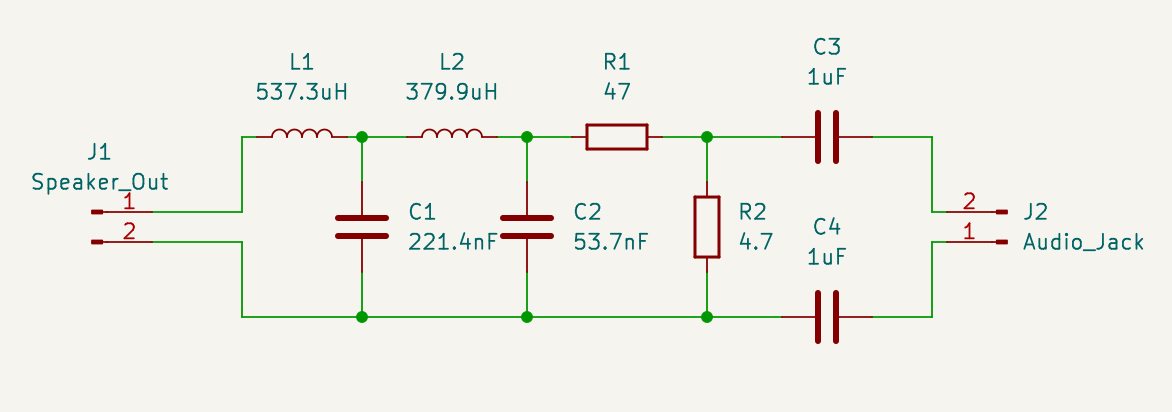
Now, there are a few problems with this:
- It’s a somewhat complicated circuit, so it will require some fiddling to put together.
- It uses ideal values instead of components that you can actually find.
- It’s untested, so it might not work at all.
The AITRIP module takes I2S input, not spdif.
That’s fine though, Proffieboards can generate I2S output.
are any components needed to enable the I2S output?
No, just wires and code.
thank you very much sir you saved my project from yet another re-design
Hello again so I have tried the above solution with no luck. Also I’m now using a proffie v3 board not sure if that changes it but I couldn’t get it going on the V2 either.
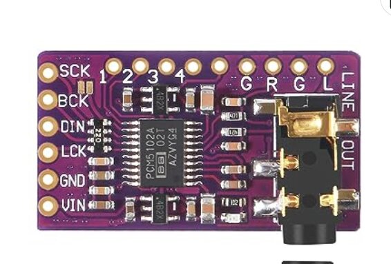
I’m using the SCK , LCK and DIN pins. The DAC powers on fine but I don’t get a signal, meanwhile if I test the analog sound from the speaker pads that still works as I imagine it should. Anyway any help would be awesome thanks
Are you using the right pins?
For a V2 board, which pin carries which signal is defined here:
For a V3 board, you should be able to find it in the pin function table table:
https://fredrik.hubbe.net/lightsaber/v6/
Make sure your config file doesn’t try to use the same pin as button or data pad.
got it thanks for sticking with me. For anyone else it ended up being that the BCK needed to be used in place of the SCK pad.