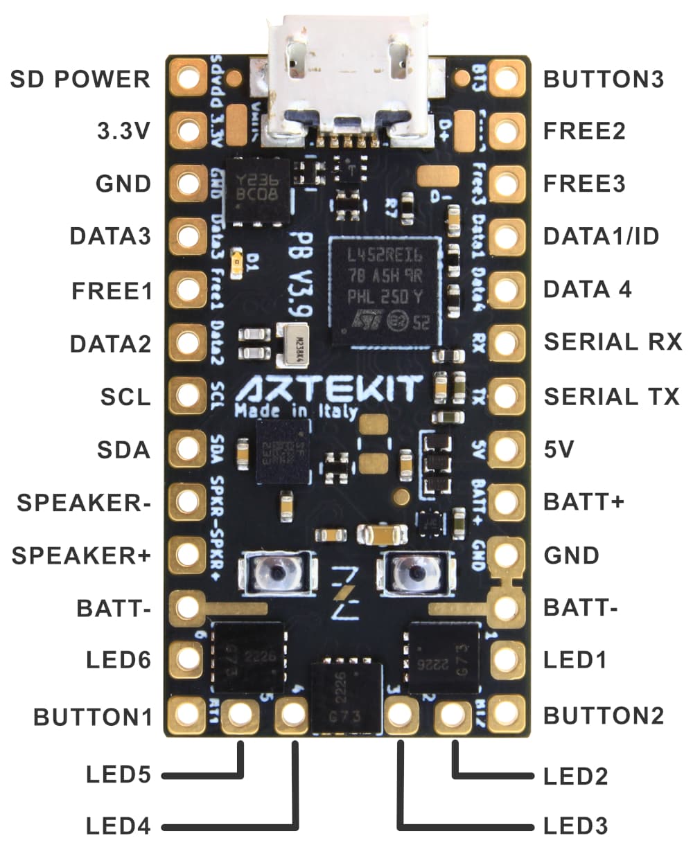
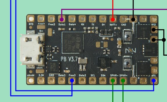
I can give you a bit more later if you need it, but the Proff’s configurator is very helpful in this respect. Assuming you’re using a V3.9 for your Proffie boards, just note that the image there is of a 3.7 so slightly off on pinout. I find the Artekit site helpful in this regard:
Based on the configurator images for diagram, here are the two variations you’re talking about along with some additional details I found in my builds.
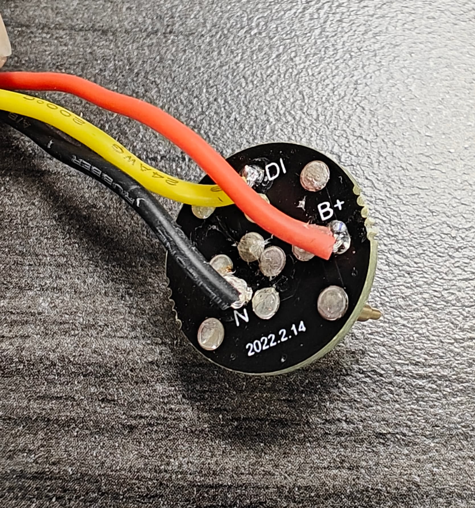
Baselit
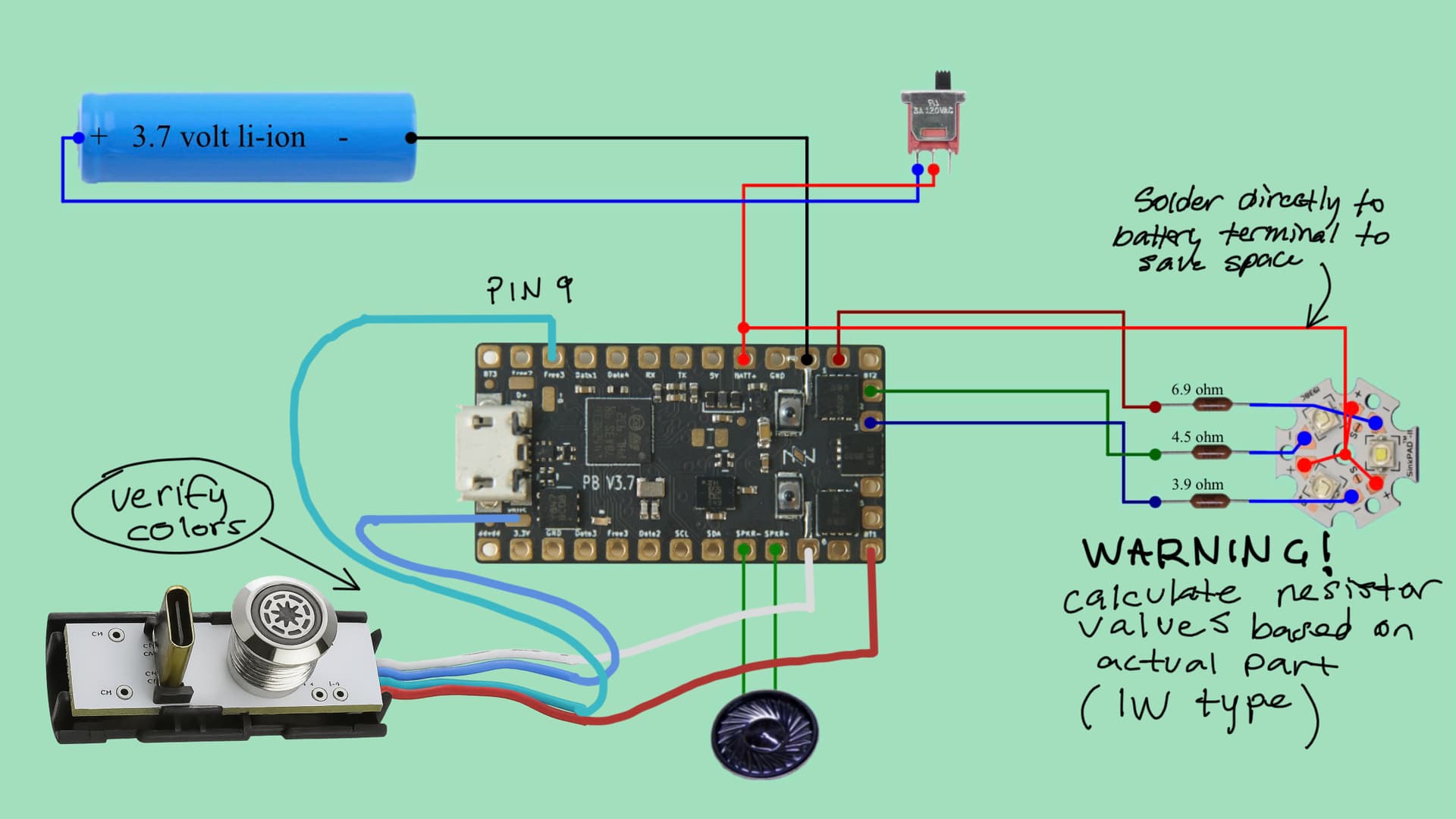
This image shows upgrading a baselit saber without changing out to a pixel… I prefer the pixel but a baselit with a proffie is way better than the cheap baselit it was before your build. Just know there are some adjustments to programming to accommodate this and I’m happy to help if you get there. One critical point is that your resistors should be 1W rated and be calculated based on what you actually have. Mine didn’t look like this but rather had one pixel module with 6 pads in the middle. Those are pretty typical and they have a rating of about 300-350mA which is way under the 1000mA of a nice one. They still look good though but you have to calculate a much higher resistance and source your own resistors outside of the saber shops (they carry much lower resisters for the high current tri-cree emitters). What you see in the diagram are what I used based on the emitter described. You should test your own though to be safe!
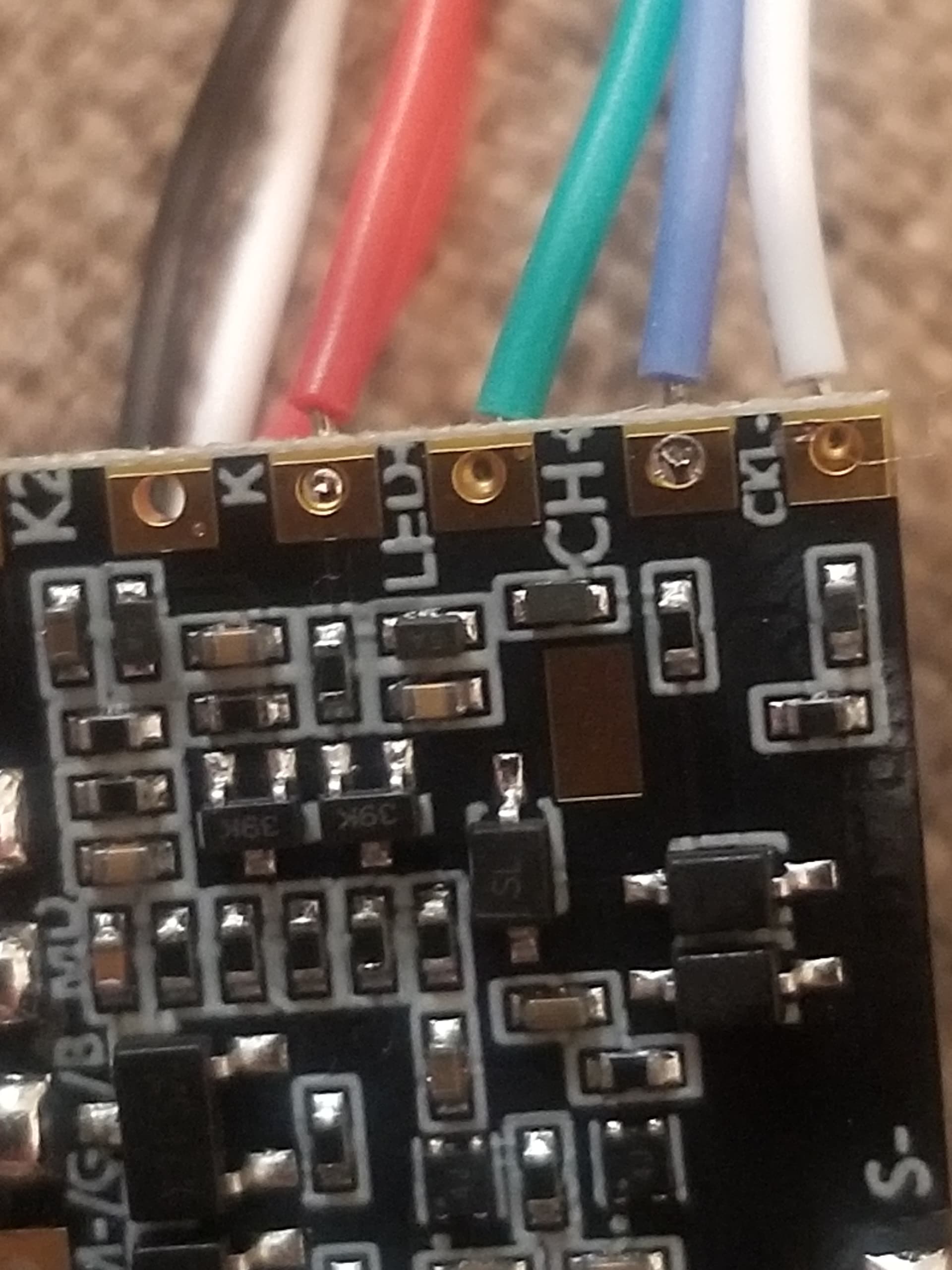
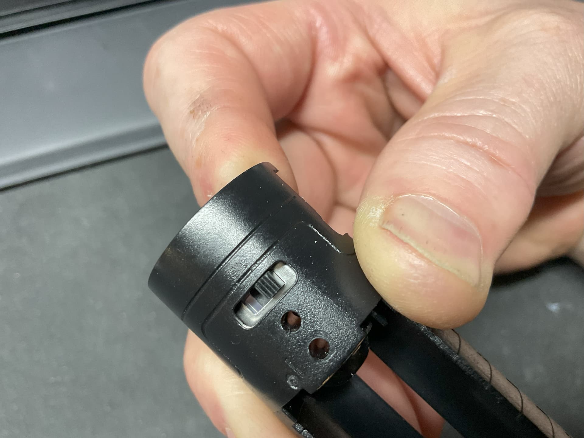
For your button/USB combo, you should verify colors like I said before, but I’m pretty sure it’s correct as I show here.
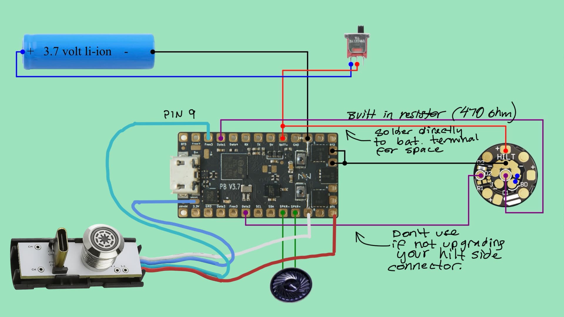
Modify the values based on your resistors, but here’s my blade config that includes both the button on pin 9 (FREE 3) and the Cree knockoff. I used 1000 for the value of the resistor on the illuminated button - the button has one built into the module and this worked well and no damage. Since this button is just an LED, there is no data or color. You set it to “White” or rgb(255,255,255) and that is full brightness in whatever color your button is. You can reduce brightness by customizing this in the style similar to what you show at the bottom of this section.
BladeConfig blades[] = {
  {
    0,
    SimpleBladePtr<CreeXPE2RedTemplate<6900>, CreeXPE2GreenTemplate<4500>, CreeXPE2BlueTemplate<3900>, NoLED, bladePowerPin1, bladePowerPin2, bladePowerPin3, -1>(),
    SimpleBladePtr<CreeXPE2WhiteTemplate<1000>, NoLED, NoLED, NoLED, 9, -1, -1, -1>(),  // Free3 (pin 9) white button LED
    CONFIGARRAY(presets)
  }
};
And as a little bonus, here’s a style you can use if you have a Vader font. I made the button pulse which looks nice on standby (just make sure you include a timeout in your top section to not kill your battery). I also used Fett263’s style builder to create a nice Vader font that works very well with the baselit setup.
 { "Father;common",  "Father/tracks/track1.wav",
    /* copyright Fett263 Rotoscope (Primary Blade) OS7 Style
    https://www.fett263.com/fett263-proffieOS7-style-library.html#Rotoscope
    OS7.14 v3.23p
    Single Style
    Style Option
    Base Color: BaseColorArg (0)

    --Effects Included--
    Preon Effect: Sparking [Color: PreonColorArg]
    Ignition Effect: Fade Up [Color: IgnitionColorArg]
    Retraction Effect: Fade Out [Color: RetractionColorArg]
    Lockup Effect:
    0: mainLockMulti0Shape - Begin: Full Blade Flash - Style: Intensity AudioFlicker - End: Full Blade Absorb
    [Color: LockupColorArg]
    Lightning Block Effect:
    0: mainLBMulti0Shape - Begin: Full Blade Flash - Style: Strobing AudioFlicker - End: Full Blade Absorb
    [Color: LBColorArg]
    Drag Effect: NoneMelt Effect: NoneBlast Effect: Full Blade Blast Fade [Color: BlastColorArg]
    Clash Effect: Flash on Clash (Full Blade) [Color: ClashColorArg]
    Battery Level: Full Blade (Green to Red)
    Display Volume: % Blade [Color: BaseColorArg]
    */
    StylePtr<Layers<RandomFlicker<Stripes<10000,-2600,RgbArg<BASE_COLOR_ARG,Rgb<255,0,0>>,RgbArg<BASE_COLOR_ARG,Rgb<255,0,0>>,Mix<Int<7710>,Black,RgbArg<BASE_COLOR_ARG,Rgb<255,0,0>>>,RgbArg<BASE_COLOR_ARG,Rgb<255,0,0>>,Mix<Int<16448>,Black,RgbArg<BASE_COLOR_ARG,Rgb<255,0,0>>>>,RgbArg<BASE_COLOR_ARG,Rgb<255,0,0>>>,TransitionEffectL<TrConcat<TrJoin<TrDelay<30>,TrInstant>,RgbArg<BLAST_COLOR_ARG,Rgb<255,255,255>>,TrFade<300>>,EFFECT_BLAST>,TransitionEffectL<TrConcat<TrJoin<TrDelay<30>,TrInstant>,RgbArg<CLASH_COLOR_ARG,Rgb<255,255,255>>,TrFade<300>>,EFFECT_CLASH>,LockupTrL<TransitionEffect<AudioFlicker<RgbArg<LOCKUP_COLOR_ARG,Rgb<255,255,255>>,Mix<Int<12000>,Black,RgbArg<LOCKUP_COLOR_ARG,Rgb<255,255,255>>>>,AudioFlicker<RgbArg<LOCKUP_COLOR_ARG,Rgb<255,255,255>>,Mix<Int<20000>,Black,RgbArg<LOCKUP_COLOR_ARG,Rgb<255,255,255>>>>,TrExtend<5000,TrInstant>,TrFade<5000>,EFFECT_LOCKUP_BEGIN>,TrConcat<TrInstant,RgbArg<LOCKUP_COLOR_ARG,Rgb<255,255,255>>,TrFade<300>>,TrConcat<TrInstant,RgbArg<LOCKUP_COLOR_ARG,Rgb<255,255,255>>,TrFade<400>>,SaberBase::LOCKUP_NORMAL,Int<1>>,LockupTrL<Strobe<RgbArg<LB_COLOR_ARG,Rgb<255,255,255>>,AudioFlicker<RgbArg<LB_COLOR_ARG,Rgb<255,255,255>>,Blue>,50,1>,TrConcat<TrExtend<200,TrInstant>,RgbArg<LB_COLOR_ARG,Rgb<255,255,255>>,TrFade<200>>,TrConcat<TrInstant,RgbArg<LB_COLOR_ARG,Rgb<255,255,255>>,TrFade<400>>,SaberBase::LOCKUP_LIGHTNING_BLOCK,Int<1>>,InOutTrL<TrFadeX<BendTimePowInvX<IgnitionTime<0>,Mult<IntArg<IGNITION_OPTION2_ARG,10992>,Int<98304>>>>,TrFadeX<BendTimePowX<RetractionTime<0>,Mult<IntArg<RETRACTION_OPTION2_ARG,10992>,Int<98304>>>>,Black>,TransitionEffectL<TrConcat<TrInstant,AlphaL<BrownNoiseFlickerL<RgbArg<PREON_COLOR_ARG,Rgb<255,255,255>>,Int<30>>,SmoothStep<Scale<SlowNoise<Int<2000>>,IntArg<PREON_SIZE_ARG,2000>,Sum<IntArg<PREON_SIZE_ARG,2000>,Int<4000>>>,Int<-2000>>>,TrDelayX<WavLen<EFFECT_PREON>>>,EFFECT_PREON>,TransitionEffectL<TrConcat<TrJoin<TrDelay<2000>,TrInstant>,Mix<BatteryLevel,Red,Green>,TrFade<300>>,EFFECT_BATTERY_LEVEL>,TransitionEffectL<TrConcat<TrExtend<2000,TrWipe<100>>,AlphaL<RgbArg<BASE_COLOR_ARG,Rgb<255,0,0>>,SmoothStep<VolumeLevel,Int<-1>>>,TrFade<300>>,EFFECT_VOLUME_LEVEL>>>(),
    StylePtr<Pulsing<Rgb<50,50,50>,White,8000>>(),
    "Darth Vader"
  }
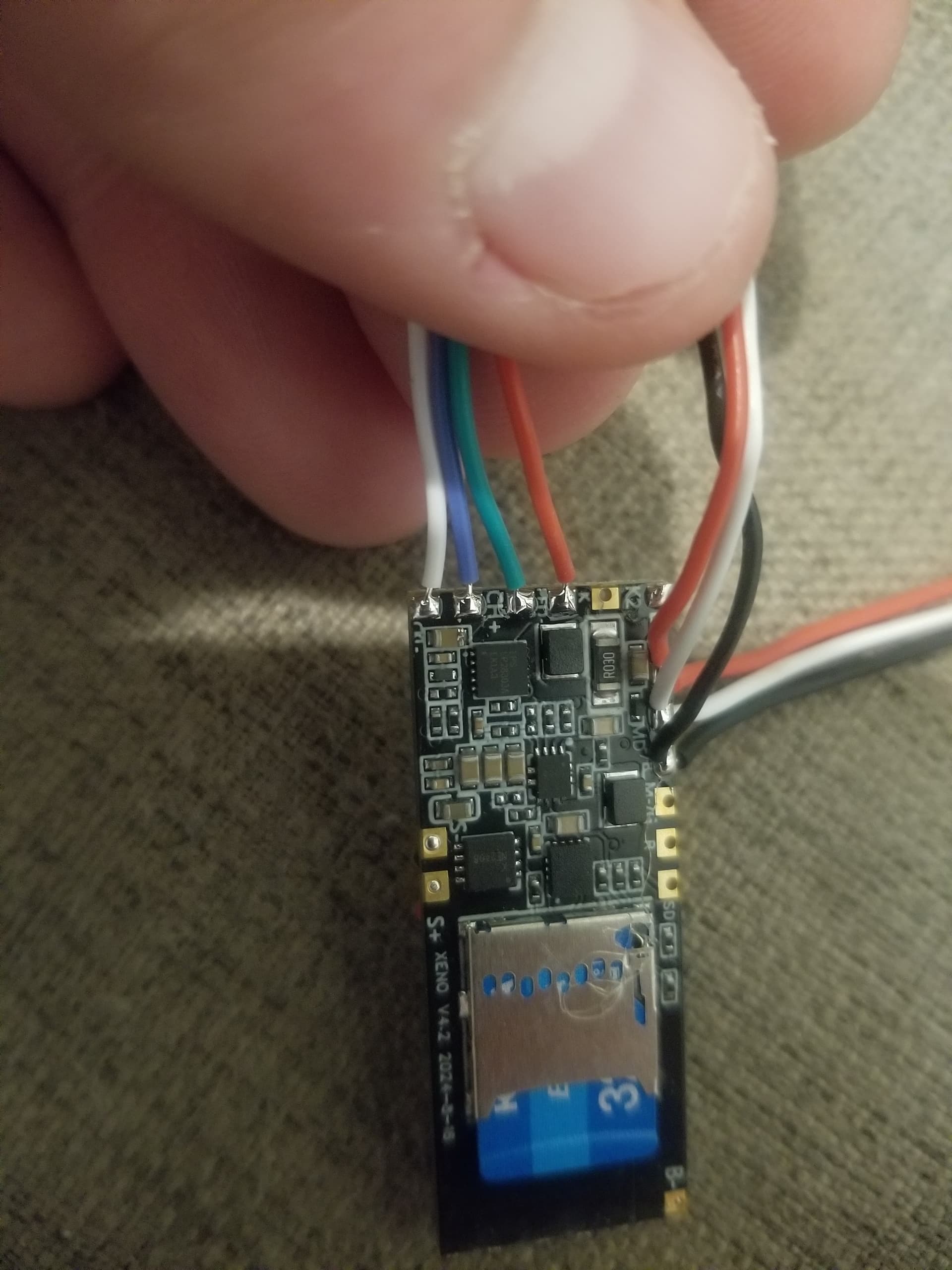
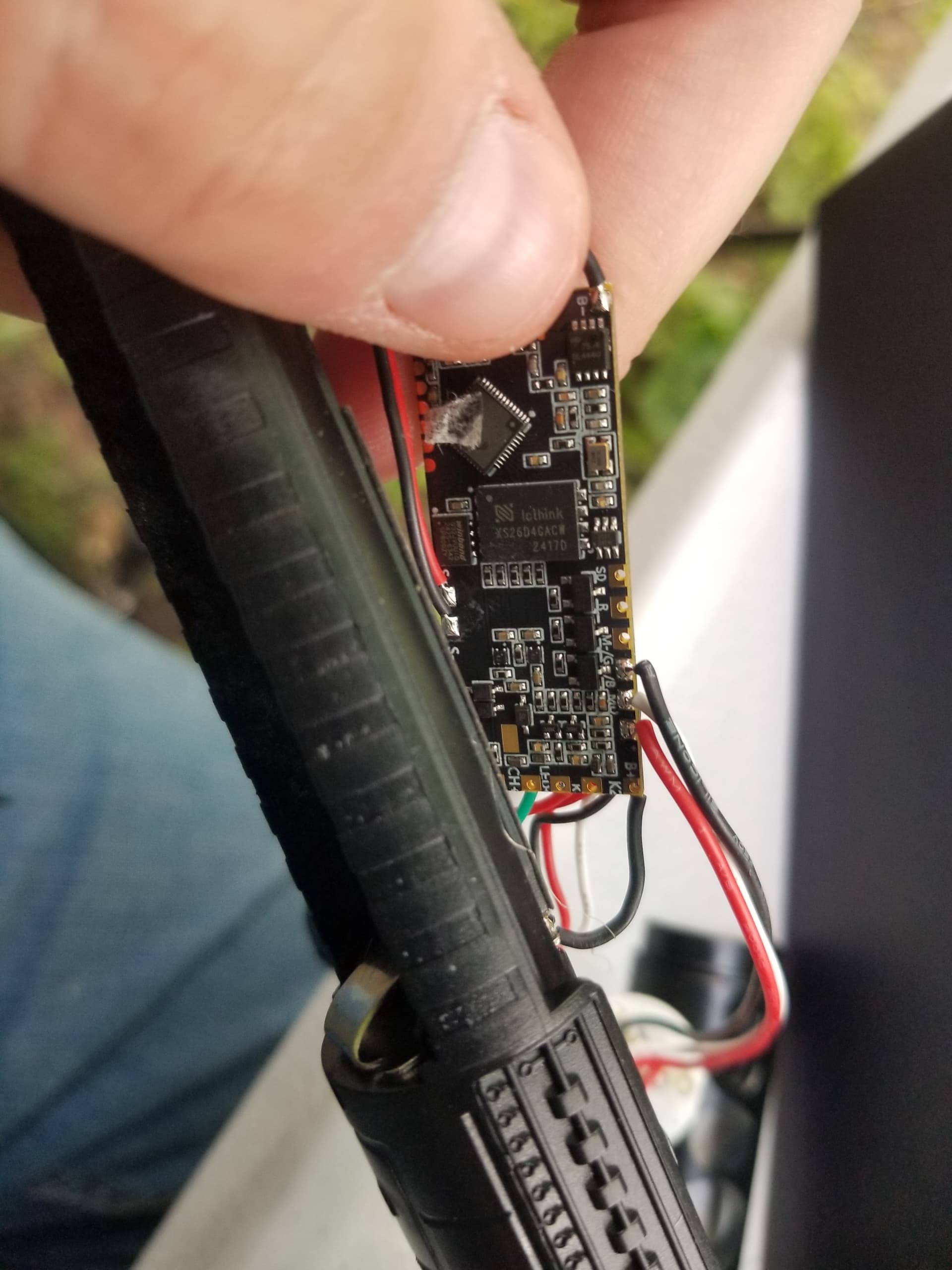
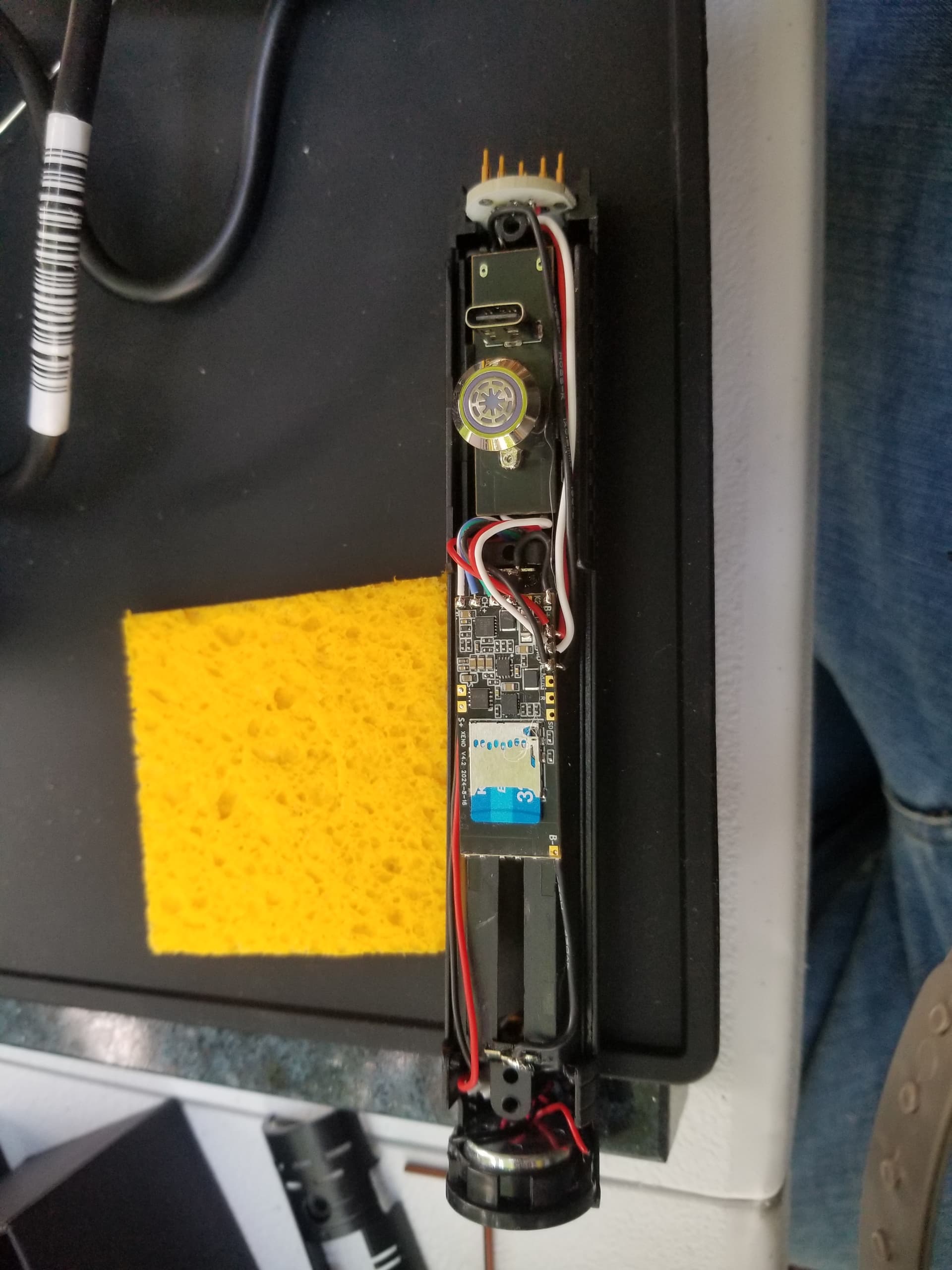
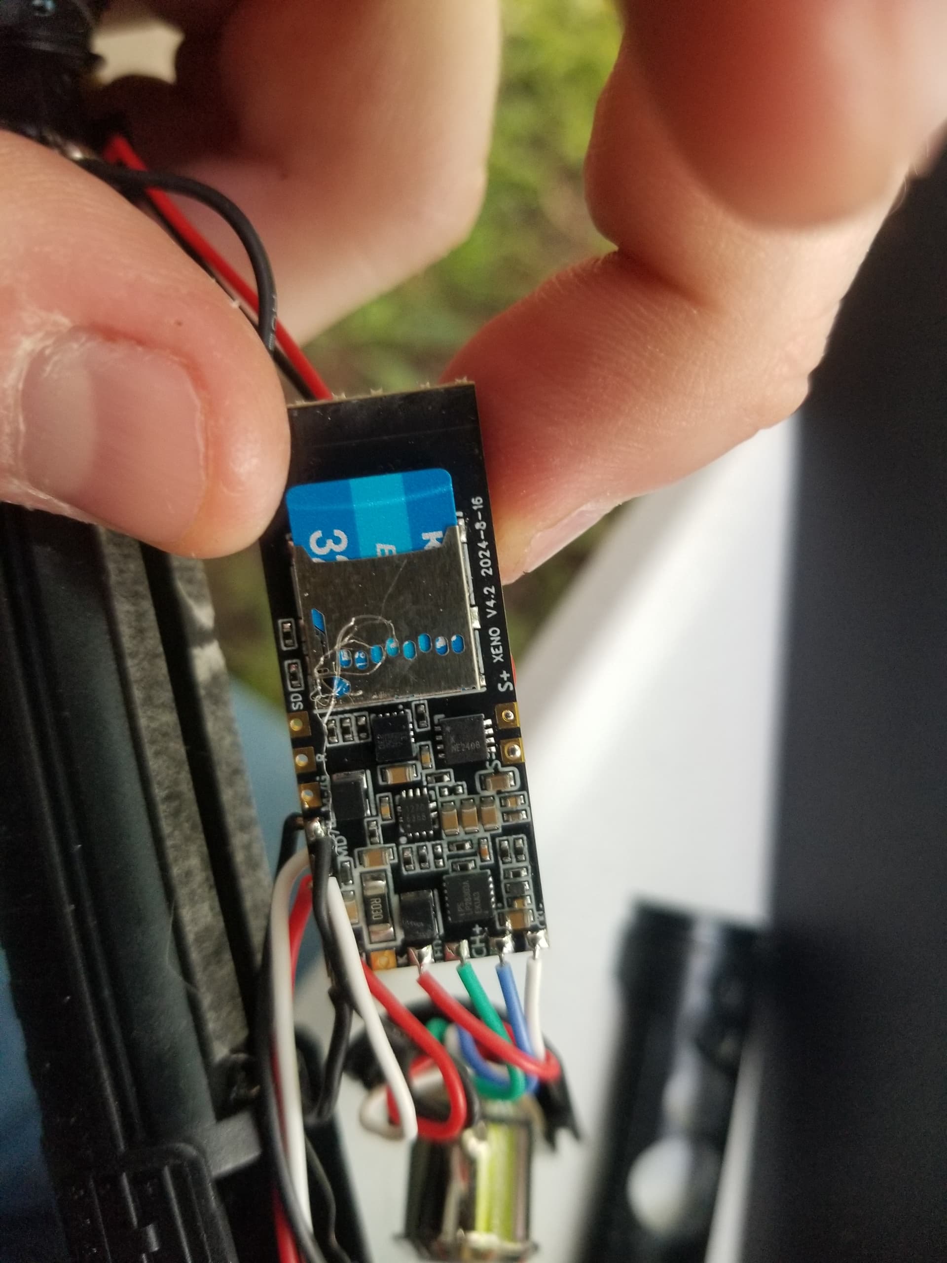
There is a spot on most xenopixel chassis by the speaker that is for a USB that you can use instead for your kill switch if you hot glue it in there at the right height to not interfere with the hilt. You will also find that the Proffie barely fits and I’ve been able to CAREFULLY sand down both sides just before getting into the solder pads to bring down the width to just under 17mm which makes it fit a little easier. I’ve also made a cutout between where the board goes and the battery compartment to give a little more space where the SD card goes. You can flip it over with the SD card on top but doesn’t really help much for space unless you ditch the USB - but you then have to change everything up so you have a way of transferring data (if you find you really want to go there PM me). The main thing here is it is critical that nothing touches the hilt when you put it on and the plastic tab won’t be any help because it’s too thick to fit the USB port under it unless you modify.
All this said, I hope all this doesn’t scare you off. It’s a good way to get going on the cheep using parts you already have. I think a custom chassis and fresh build is probably better, but this isn’t bad and gets you a proffie for the cost of the board and a kill switch… Good luck!