Configuration + Wiring for KR Sabers Master QGJ w/Metal Master Chassis

First Time DIYer - Not tech savvy

My initial configuration included below, basically listing everything available that was included in my saber:

WS2811 / Neopixel (132 LEDs per the guide)
Illuminated PCB (16 LEDs)
Neopixel crystal chamber or accents (1 LED)
Momentary Button (just one)
Kill Switch
Battery (included by default)
Speaker (included by default)

I was advised by KR Sabers that I should take off the ‘16LEDs’ from the config if I’m just going to use V2 of the NPXL PCB setup, where the PCB mirrors the blade. Furthermore, I saw on YouTube other setups where they configured the blade but excluded the PCB… basically treating the PCB as the blade itself. All this considered, I re-did my config to only list what’s actually being connected to the board (and treating PCB as the ‘blade’):

WS2811 / Neopixel (132 LEDs)
Momentary Button
Kill Switch
Battery (default)
Speaker (default)

Regardless of the connection diagram it generates, my concern is what needs to be included in the config for sake of the coding it generates for the software. Can anyone assist with the correct config I should use?

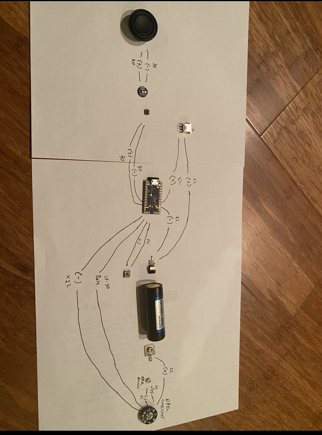
On the hardware side, I drew out what I believe to be how I need to connect the wires for all the parts. Can this be reviewed to see if accurate? Appreciate any help:

If you run the PCB pixels in parallel with the blade, then your config becomes very simple, because it doesn’t have to know about it, here is an example config that would work:

#ifdef CONFIG_TOP
#include "proffieboard_v3_config.h"
#define NUM_BLADES 1
#define NUM_BUTTONS 1
#define VOLUME 1000
const unsigned int maxLedsPerStrip = 144;
#define CLASH_THRESHOLD_G 1.0
#define ENABLE_AUDIO
#define ENABLE_MOTION
#define ENABLE_WS2811
#define ENABLE_SD
#endif

#ifdef CONFIG_PRESETS
Preset presets[] = {
   { "TeensySF", "tracks/venus.wav",
    StyleNormalPtr<CYAN, WHITE, 300, 800>(), "cyan"},
   { "SmthJedi", "tracks/mars.wav",
    StylePtr<InOutSparkTip<EASYBLADE(BLUE, WHITE), 300, 800> >(), "blue"},
   { "SmthGrey", "tracks/mercury.wav",
    StyleFirePtr<RED, YELLOW>(), "fire"},
   { "SmthFuzz", "tracks/uranus.wav",
    StyleNormalPtr<RED, WHITE, 300, 800>(), "red"},
   { "RgueCmdr", "tracks/venus.wav",
    StyleFirePtr<BLUE, CYAN>(), "blue fire"},
   { "TthCrstl", "tracks/mars.wav",
    StylePtr<InOutHelper<EASYBLADE(OnSpark<GREEN>, WHITE), 300, 800> >(), "green"},
   { "TeensySF", "tracks/mercury.wav",
    StyleNormalPtr<WHITE, RED, 300, 800, RED>(), "white"},
   { "SmthJedi", "tracks/uranus.wav",
    StyleNormalPtr<AudioFlicker<YELLOW, WHITE>, BLUE, 300, 800>(), "yellow"},
   { "SmthGrey", "tracks/venus.wav",
    StylePtr<InOutSparkTip<EASYBLADE(MAGENTA, WHITE), 300, 800> >(), "magenta"},
   { "SmthFuzz", "tracks/mars.wav",
    StyleNormalPtr<Gradient<RED, BLUE>, Gradient<CYAN, YELLOW>, 300, 800>(), "gradient"},
   { "RgueCmdr", "tracks/mercury.wav",
    StyleRainbowPtr<300, 800>(), "rainbow"},
   { "TthCrstl", "tracks/uranus.wav",
    StyleStrobePtr<WHITE, Rainbow, 15, 300, 800>(), "strobe"},
   { "TeensySF", "tracks/venus.wav",
    &style_pov, "POV"},
   { "SmthJedi", "tracks/mars.wav",
    &style_charging, "Battery\nLevel"}
};
BladeConfig blades[] = {
 { 0, WS281XBladePtr<144, bladePin, Color8::GRB, PowerPINS<bladePowerPin2, bladePowerPin3> >(), CONFIGARRAY(presets) },
};
#endif

#ifdef CONFIG_BUTTONS
Button PowerButton(BUTTON_POWER, powerButtonPin, "pow");
#endif

Some caveats:

  • This is a beginner config file, it doesn’t have edit mode, responsive styles or anything fancy. However, it would get you started.
  • The “NPXL accent” in your diagram needs a data line of some sort if it is truly a neopixel, but maybe it’s just a regular LED? (If so, maybe it needs a resistor?)
  • In your diagram, it looks like (+) goes to both ends of the battery, that seems weird.
  • Personally I prefer to hook everything up so that I can control each LED individually. It’s a little more work, but gives a lot more flexibility when setting up the software.

Sorry, having trouble with the applications (trying to quote)

‘ * This is a beginner config file, it doesn’t have edit mode, responsive styles or anything fancy. However, it would get you started’

Can you clarify what edit mode is? My understanding is that this creates an initial code configuration, then I go through Fett263 etc. to copy/paste new font codes and attach to this initial sequence. Does this sequence not allow this, or is edit mode something else?

‘* The “NPXL accent” in your diagram needs a data line of some sort if it is truly a neopixel, but maybe it’s just a regular LED? (If so, maybe it needs a resistor?)’

Here’s the guide I have for the chassis: https://goth-3designs.com/instructions/diy-kr-master-qgj-2023-master-chassis/

I probably do need to add, but the guide only says ‘install.’ Per Step 2, ‘the pixel is wired in series with the main NPXL connector. The positive and negative wires will be soldered directly to the NPXL connector’

Based on the guide maybe you can confirm? There’s three pads on the single LED so maybe I do need to add a data line.

‘* In your diagram, it looks like (+) goes to both ends of the battery, that seems weird.’

This was the part that confused me the most. I would think I somehow need to connect the (+) and (-) of the battery to the board, but the design of the chassis does not have a path from the battery (+) tab to the board. Does it make sense that I would have two connectors from the battery (-) tab, one that goes to the battery (-) on the board, and one that goes to the kill switch, which goes to the battery (+) of the board?

‘* Personally I prefer to hook everything up so that I can control each LED individually. It’s a little more work, but gives a lot more flexibility when setting up the software.’

From what I can tell, the ability to wire ‘everything’ of very limited with this chassis. It’s two separate parts, and the wires have to go through very narrow tubes to connect from the front portion to the back portion

Just highlight and press the quote button. :slight_smile:

Edit mode is a feature of the Fett263 prop which lets you change a lot of things using menues on the saber itself, no websites or config files needed.

The tool you’re talking about is Fett263s configuration generator, which I don’t know that much about, but I think you’re right that it can generate a more feature rich configuration file from a simple one. Of course Fett263s configuration generator will generally use Fett263s prop file and also enable edit mode by default.

The guide is very brief and assumes that people knows what they are doing. Since they call it a “Pixel”, and say that it is wired in parallel with the blade, I would assume that it needs three wires: +, - and data.

No, that does not make sense. The wire between the kill switch and the battery would need to go to the + side of the battery.

There’s always magnet wire, but if you don’t want to fiddle with that in your first install, that’s understandable. :slight_smile: