Config generator question/potential issue

Unless there is something that I do not understand, when using the proffieboard config generator, it generates a config file defining three blades when I only have two: the main blade and the neopixel connector. I thought it was blade detection causing it, so I turned that option off, but the three blades remained defined in the config file. Do you have any insight on what that third blade could be, or if this just a bug in the config generator? Thanks!

Attached is the config file generated by the proffieOS configurator as well as a screenshot of the options I have selected
proffie_config.txt (3.7 KB)

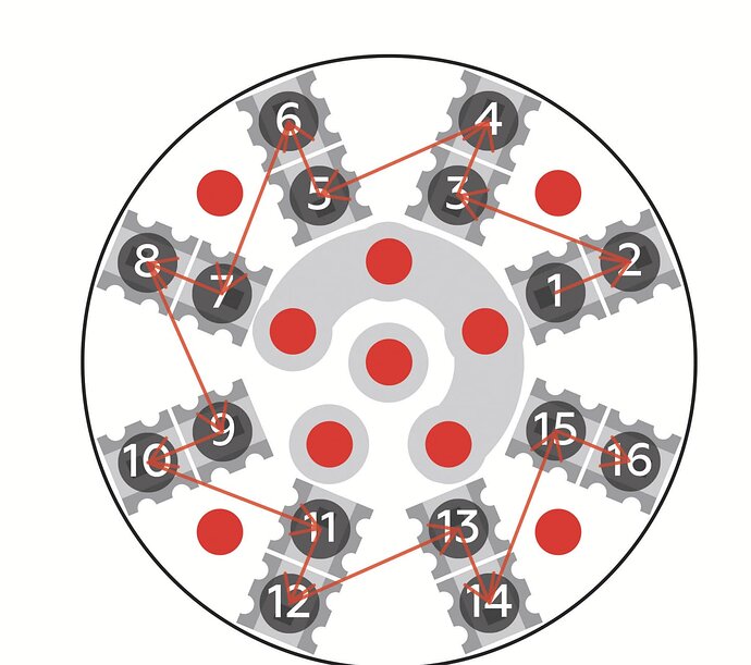
It generates two blades for the blade connector, one for the outer ring and one for the inner ring.
Not all blade connectors are wired that way though. I should probably make it optional…

Gotcha. I figured it had something to do with using blade detect before. I guess it didn’t even cross my mind since the connector I’m using (Shtok v3) shows this signal path in the user manual:


do you think a sequential signal path like this would still cause the multiple-blade issue?

It’s not an issue, it is by design.
The two blades are designed for exactly this pogo pin pcb.
ProffieOS does not know what is actually connected, all it knows about the pixels comes from the blades[] array.

Okay. Thanks for the guidance :slight_smile:

Make it optional, or explain it in comments in the config why 2 blades are created for the NPXL V3 connector instead of one. Maybe the config generator could generate something like this:

BladeConfig blades[] = {
 { 0,
    // === Main Blade: ===
    WS281XBladePtr<144, bladePin, Color8::GRB, PowerPINS<bladePowerPin2, bladePowerPin3> >(),
    // === Main NPXL Connector "inner ring": ===
    SubBladeWithStride(0, 15, 2, WS281XBladePtr<16, blade2Pin, Color8::GRB, PowerPINS<bladePowerPin2, bladePowerPin3> >()),
    // === Main NPXL Connector "outer ring": ===
    SubBladeWithStride(1, 15, 2, NULL),
    CONFIGARRAY(presets) },
 { NO_BLADE,
    // === Main Blade: ===
    WS281XBladePtr<144, bladePin, Color8::GRB, PowerPINS<bladePowerPin2, bladePowerPin3> >(),
    // === Main NPXL Connector "inner ring" ===
    SubBladeWithStride(0, 15, 2, WS281XBladePtr<16, blade2Pin, Color8::GRB, PowerPINS<bladePowerPin2, bladePowerPin3> >()),
    // === Main NPXL Connector "outer ring" ===
    SubBladeWithStride(1, 15, 2, NULL),
    CONFIGARRAY(no_blade_presets), "nb_save" }
,
};

Or if you want to keep it simple just one comment between the two NPXL subblades:

// two blades created for the NPXL connector, one for inner & the other for outer ring.

It would certainly have removed a lot of confusion on my part when I first started.
And I am pretty sure I am not the only one who could have benefited from a simple comment in the config generator.