I’ve just built a WarSabers Starkiller hilt and the very impressive kit includes an onboard USB charging system.
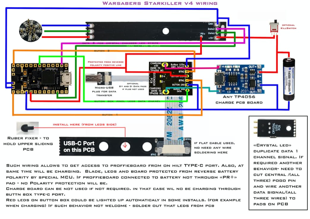
If you look at the first diagram below, it shows how it works, using a TP4056 charge PCB.
It works great, except for two details:
The first is the red LEDs mentioned in the bottom paragraph on the diagram. They stayed lit the whole time the hilt was powered which was a pain, so I removed them. This leaves no charging indicator as such. Not a huge problem, but a niggle.
But the second problem is potentially more serious. I’ve read that TP4056 boards should not be wired such that the component load is being drawn at the same time as the battery is charging. However in this case, it is possible to do just that. If you leave the kill switch to ON and plug the charger cable in, the Proffie will be powered while the battery is charging, potentially, I’m guessing, confusing the TP4056 into thinking the battery is not yet full when in fact it is.
My theory knowledge isn’t good enough to know whether this is likely or if it’s an issue or not. For a project we might build for ourselves, it’s not a problem - we just have to remember to have the kill switch OFF for charging. But building a hilt for someone else, it really needs be bullet proof and idiot proof.
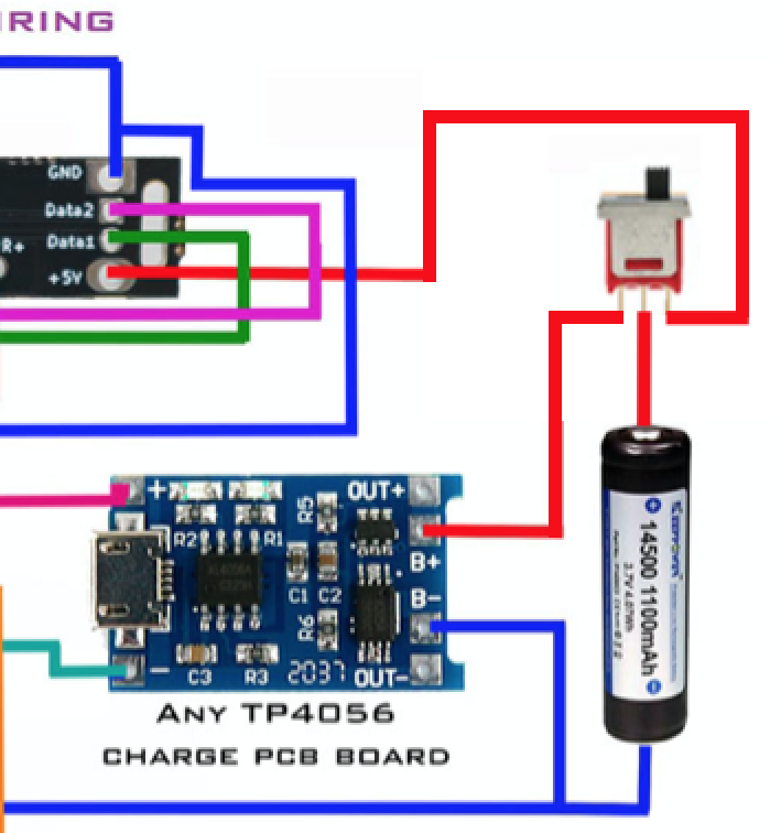
So it occurs to me that if I rewire the kill switch as per the second diagram, it can only ever be an either/or situation: either the battery is set up to charge and the Proffieboard is powered down, or the Proffieboard is powered up and the charging system is disconnected.
So my question is, would this work and is it necessary?
What have I missed?
Thoughts welcome.

Your second pic is what I’d do for sure.
1 Like
Been doing some more research and my wiring modification does indeed seem like the way forward. However I just noticed another anomoly: I took a partially discharged battery (which was reading 3.5 volts) and put it in the hilt, then connected the charge cable. Voltage at the battery terminals with the charge cable connected then showed 3.7 volts. But surely it should have shown 4.2 volts?
Shouldn’t it?

At the TP4056’s input from the charger, you should see charger voltage.
I don’t know those boards particularly, but I’d assume it’s “smart” and slowly charging the battery, so you’d only see a little difference at a time.
1 Like
***** UPDATE *****
Just updating this in case anyone is interested, but I’ve done a few more tests on this with the following conclusions:
My proposed mod works well and does successfully make the charge circuit an either/or situation with the kill switch. However the down side is that you need to open the hilt to access the switch every time you want to charge the hilt. Since the charge port is on the outside of the hilt (built into the switchbox) this seems a shame.
So I tried wiring the hilt as per WarSabers standard diagram. I also removed the two status LEDs on the TP4056 board and extended them out to an external charge status LED.
What this meant is that the TP4056 would charge the battery regardless of whether the Proffie was powered or not.
As mentioned earlier, the concern was that the Proffie power draw would confuse the 4056 into not correctly reading when the battery is full.
The good news is, having now tested it, I can confirm that it charges successfully with the Proffie powered. I put a half charged battery in there and plugged in the external USB to charge it. At first my status LED was red, then after a few hours it turned green showing full charge. The Proffie was powered throughout, although I did set the idle time out feature so that no Proffie LEDs were powered for most of the charge time.
So it looks like the standard wiring setup gives the most user flexibility, to no ill effect in terms of other functions.
I’ve been working through the USB charging options for my builds as well–protected batteries, non-protected batteries, usb charging boards, independent protection chips… and I think the first wiring works in your scenario because of the TP4056 board in the picture includes the 8205 chip. There is a smaller USB charging board that only have the TP4056 chip and does not have the 8205 protection chip.
I’ve been struggling with this on my build and wanted to ask: are you using a V2.2 board or a V3.9 board? I’ve read that the 3.9 includes onboard USB charging, so I would only need to have a passthrough from the 3.9’s micro USB to my external USB C–but I have also heard that it either doesn’t work or isn’t recommended–and it definitely seems it would take longer to charge than a TP4056 charging board. Any insight from your recent build? I was hoping to avoid a TP4056 board since I’m including a 1S 15A battery protection circuit, which is taking up some space–but I could squeeze in the smaller TP4056 board if it is a big advantage over the 3.9’s built-in charging.
THe 3.9 charge is fairly slow at 450mA. If that matters to you, you’ll need an external charger somehow.
1 Like
All of these charging hilts that I’ve built have used a Proffie 2.2. And yeh, there are a couple of different version of the 4056 board, but usually one is supplied with the hilt kit, so I assume they spec the correct version.
As for 3.9 charging, I’ve not done it, but I think it’s just there and you don’t need to do anything (correct me if I’m wrong Prof.), it just works a bit slower as the Prof says.
2 Likes