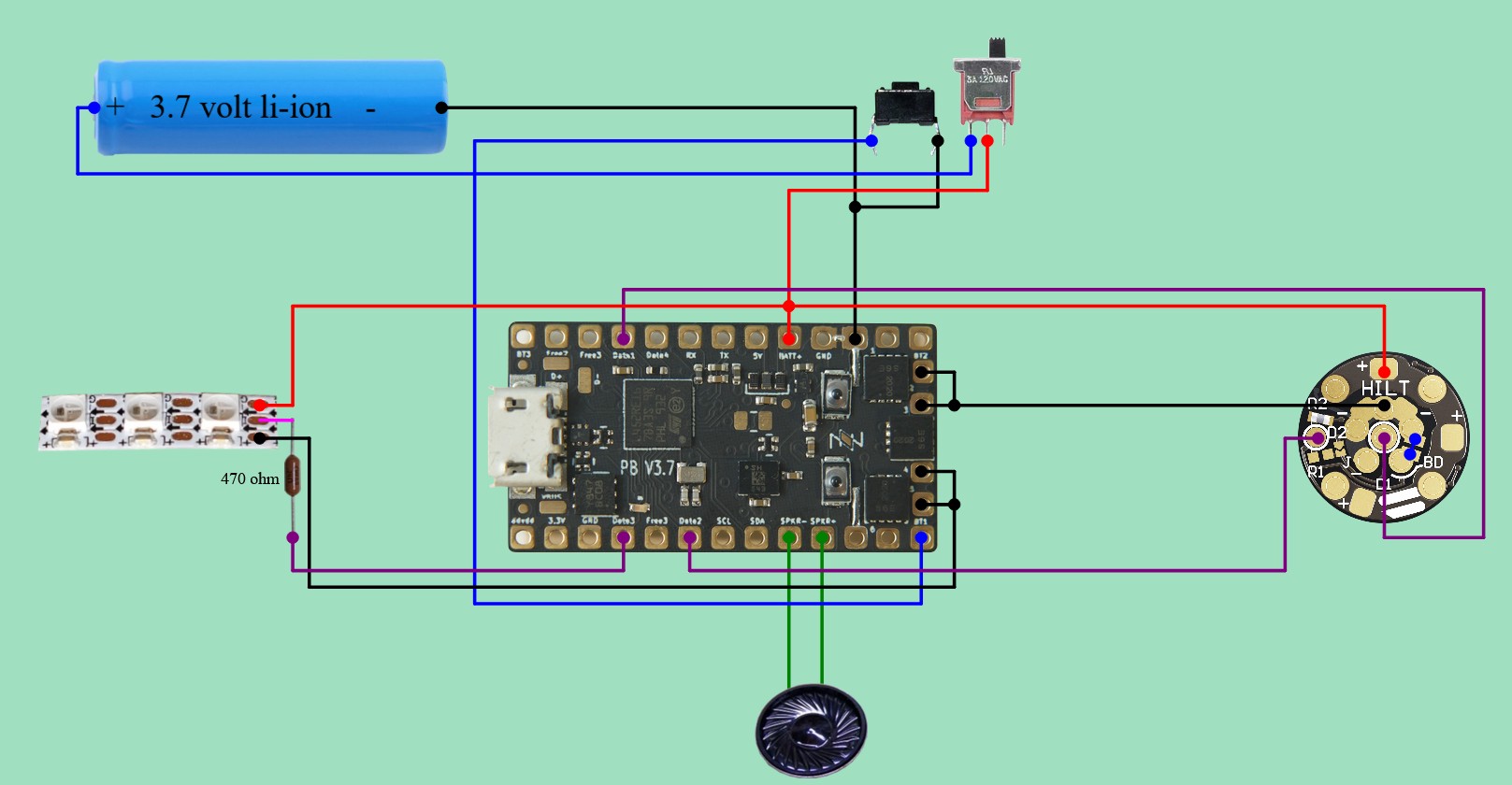
Hey all, struggling with my first saber. I’ve got a NPXL V4 Hiltside Pixel Connector and two Neopixel Accent LED Single Pixels for a Crystal Chamber. I followed this wiring diagram from the generator:
This has the Pixel Connector work correctly, but nothing from the Crystal Chamber’s accent LEDs. I asked a friend about it and he recommended removing the wire from D1 to Data1 and changing the config to this;
no change, it looks like. The Pixel Connector still lights up without D1, but the accent lights are still inactive.
I’ve torn it apart and checked the wiring twice, nothing is getting bridged where it shouldn’t and I’m following the data direction in/out line on the accent LEDs correctly so I’m assuming this is a config issue, any advice? Cheers!
Edit: welp I finally thought to whip out the multimeter and I lose continuity in the data line at the first accent LED. That seems like a problem! All the solder points are good and I have continuity either side so the break is the LED itself.
A couple thoughts for you as you continue to troubleshoot. First, make sure you have voltage at your pixels and that they aren’t wired backwards. Since you’ve checked wiring a bunch this is probably fine, but it’s worth a quick multimeter check.
Then, since your NPXL is lighting from Data 2 (if I understood you right), I’d temporarily solder that same data line over to your crystal chamber’s data-in. Leave your config as is so the chamber’s power pads stay active. If those two pixels have power and are good, they’ll light up with whatever the first two pixels of your style are doing. If they light, your problem is on the Data 3 side. If they stay dark, it’s power or the pixels themselves.
Also, you don’t need two MOSFETs (power pins 4 and 5) for just two pixels. One is fine. It won’t hurt anything to use both, but sharing the load like that is for the high amps of a blade, like your power pins 2 and 3.
One clarification that isn’t related to your Data 3 situation: in that wiring diagram, running both D1 and D2 depends on R1 being desoldered from the NPXL connector itself. They typically ship with R1 installed, which joins the two data lines, so with both wired the board’s two data outputs end up driving against each other. You don’t need both lines. Using them (with R1 removed) just unlocks some extra patterns on the NPXL accents independent of the blade.
D1 to Data1 is for the main blade.
It makes sense that the PXL connector lights up without it, however, you’ll need to check the manual for your connector to make sure it is wired correctly. (In some instances you’ll need to remove a resistor from the pixel connector when using two separate data wires.)
However, none of this should affect the crystal chamber, which I assume is represented by the left pixel strip in this circuit diagram. (The generator seems to be configured for two blades rather than blade+crystal chamber, but it makes very little difference.)
Note that data wires are not continous in a pixel strip. Each chip has an IN and an OUT for data, so it would make sense for the multimeter to not show that as connected. As mentioned, this also means that the direction of the pixel strip matters, make sure you have it connected the right way.
I figured it out! Turns out the accent LEDs were both duds / burned out. Maybe I soldered em too much? Not really sure what killed em. I swapped em for a fresh pair and it suddenly works, whoo!
Now to get it all inside the core without breaking anything.