Hi everyone. New to this community and hobby. I am diving into this and still learning a lot. Just when I think I might know enough to start my build, the universe lets me know in fact I don’t have all the facts.
I am gutting my Electrum Scion and will be putting in a 3d printed chassis and proffie 3.9v
When I use fredrik.hubbe.net for a basic build out the PCB image is throwing me into a loop and this is where I am getting stuck.
Is the Illuminated PCB the PCB that has the pogo pins that the blade PCB plate touches in this photo (the common fredrik build out for 3.9v)?
This is where I am getting confused, Smugglers Out post makes the 3d printed chassis for this saber and they have a build list. One of those parts is a S.O. 14-Pin Pixel/Switch Rotary PCB Set and this will be a removable chassis build.
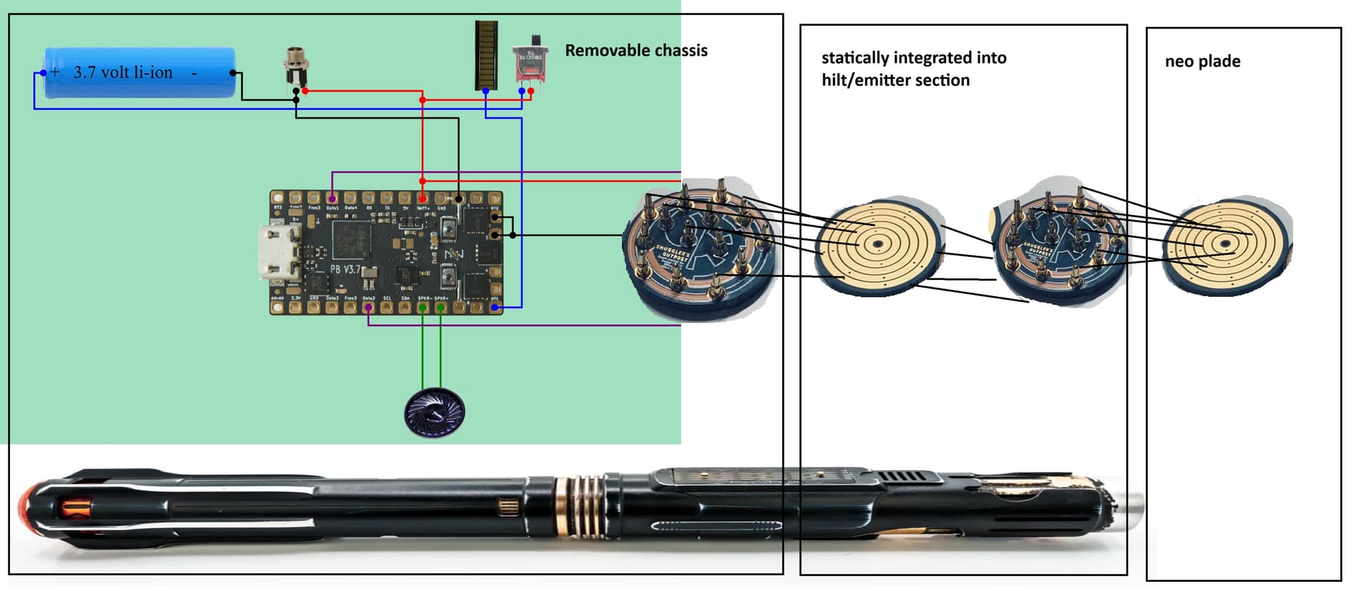
Because of it being a removeable chassis, am I doing the pogo pin PCB to rotary PCB set “twice” where the first set is pogo PCB on the end of the chassis touching the rotary PCB, rotary to another pogo PCB that this touches a rotary on the blade (This would be the second set)? If true that second PCB set ( first rotary to second pogo PCB) would statically be housed in the emitter section of the saber?
The photo uploaded is what I think the hardware I’ll need to complete this project?
You have the chassis to hilt correct, the 14 pin can be used there. And yes, it would remain in the hilt statically, back to back with the next PCB. However, the blade PCB set is just a 3 contact one (3 paths POS, NEG, Data) although there are multiple pins for each arranged in the ring configuration.
The Shtok NPXL is an example of a blade PCB that is illuminated. They come in different flavors from different vendors. Everything from plain and up.
https://www.thecustomsabershop.com/Blades/Pixel-Blades/Pixel-Blade-Components/TCSS-Style-Connector/Pre-Soldered-Pixel-PCB-Hilt-side-connector-and-7-short-pins
https://www.thecustomsabershop.com/Blades/Pixel-Blades/Pixel-Blade-Components/NPXL-Style-Connector/Pre-Soldered-NPXL-V3-Hilt-side-PCB-connector-Long-Pins
1 Like
@NoSloppy thank you for confirming what I was chasing and also that distinction between the different types of hilt PCBs as well as correcting me on the blade three ring PCB.
As I explored different builds and shops it became apparent how many different styles of parts there are. Even all my sabers do it differently from each other. So in other words many ways to skin a cat.
Last question since you pointed out the 14 pin ultimately touches a three ring device. Are the extra pinouts from chassis to blade for accessories, extra data, etc? They’re there for if you need them sorta thing? I don’t have to use all of them in other words.
Thank you again, I think my approach will be to follow the parts list for this first build and tinker outside that template to learn.
SInce hilts all completely vary, there’s no set way to do things.
So some chassis have tactile switches on them and the hilt uses plunger style, spring loaded buttons to press them. Some hilts have the tactile buttons mounted in them as part of what remains in the hilt, and then the electronic aspect is sent through to the removable chassis->board. (that’s where your multiple pins help out).
So for example, if your hilt has 2 permanent buttons, 2 permanent accent neopixel LEDs, and the main blade, you will need to connect all those lines from the hilt to the chassis, so a multi-pin PCB (14pin for example) is a good way to handle that. Of course you do not NEED to use all of them.
They’re usually labeled somewhat, like B1and B2 for 2 buttons, but if you don’t have a 2nd button, B2 would not be needed, or could be used for anything else instead.
Depending on whether you have quillon blades, whether you’re using SubBlade or not, whether there are any accent LEDs etc… will determine what you hook up or don’t.
At minimum, you’ll need 3 to get to the main blade.
chassis
1 Like
That’s such awesome break and confirmation thank you. I think that’s what I needed to hear to fully feel comfortable to attempt this.