so managed to do a bit more work towards finding the culprit and had some disappointing results.
while I was at it I upgraded to OS 5.9 just to see if that would work by itself, but alas that did not do the trick.
next I reduced the volume in my config to 1500 and again no joy.
I did as you suggested @A_Rogue_Child and replaced the swingh, swingl and swing files to see if that would work. (I swapped them out each file one by one and then all of them together)
i even swapped the hum file to see if that would help.
now I swapped them with a font I know works even at low voltage from the battery and I’m still getting some distortion.
it is a bit less than what I was getting from the TFA GRAFLEX font.
so I’m totally confused now.
could this maybe have something to do with my config setup?
its just plain weird that this is the only blade/font on my config to be suffering from this.
I did have a look at the sound files in audacity and all the swing files are just under the 0dB limit, and I think this is normal from my recollection.
@profezzorn, the 5v external supply, could this be done by plugging in a usb while the board is on?
would this supply the 5v needed to check the switch mode for operation?
so I took the font files that seem to be causing the issue, swngh, swngl and swng and ran them through audacity normalising them to -6dB and put them on the SD card.
this seems to have done the trick… only a slight bit of distortion but only on the odd occasion.
not sure if this was the genuine cause or if this was just a wok around (I’m guessing the latter) but it seems to be working much better now.
could it be that as multiple tracks were playing that the amp is being stressed?
I think it was mentioned above that running a large speaker would stress the amp so am wondering if running the 8ohm version might be better for this size of speaker?
Finally got hold of a regulated power supply off my dad and found the time to test the board.
soldered some rather long wires to the +5v pad and GND so I could swing the saber.
first test. full battery… worked as expected.
second test. half battery… as expected, the strange over drive / distortion can be heard.
third test, psu turned on… problem solved! it works flawlessly!
Now, soldering QFN components basically requires a hot-air soldering station, but those can be picked up for less than $50 and can be used for lots of things. You may also need some soldering paste. Usually it’s best to clean off some of the existing solder and replace with fresh solder paste when doing SMT soldering.
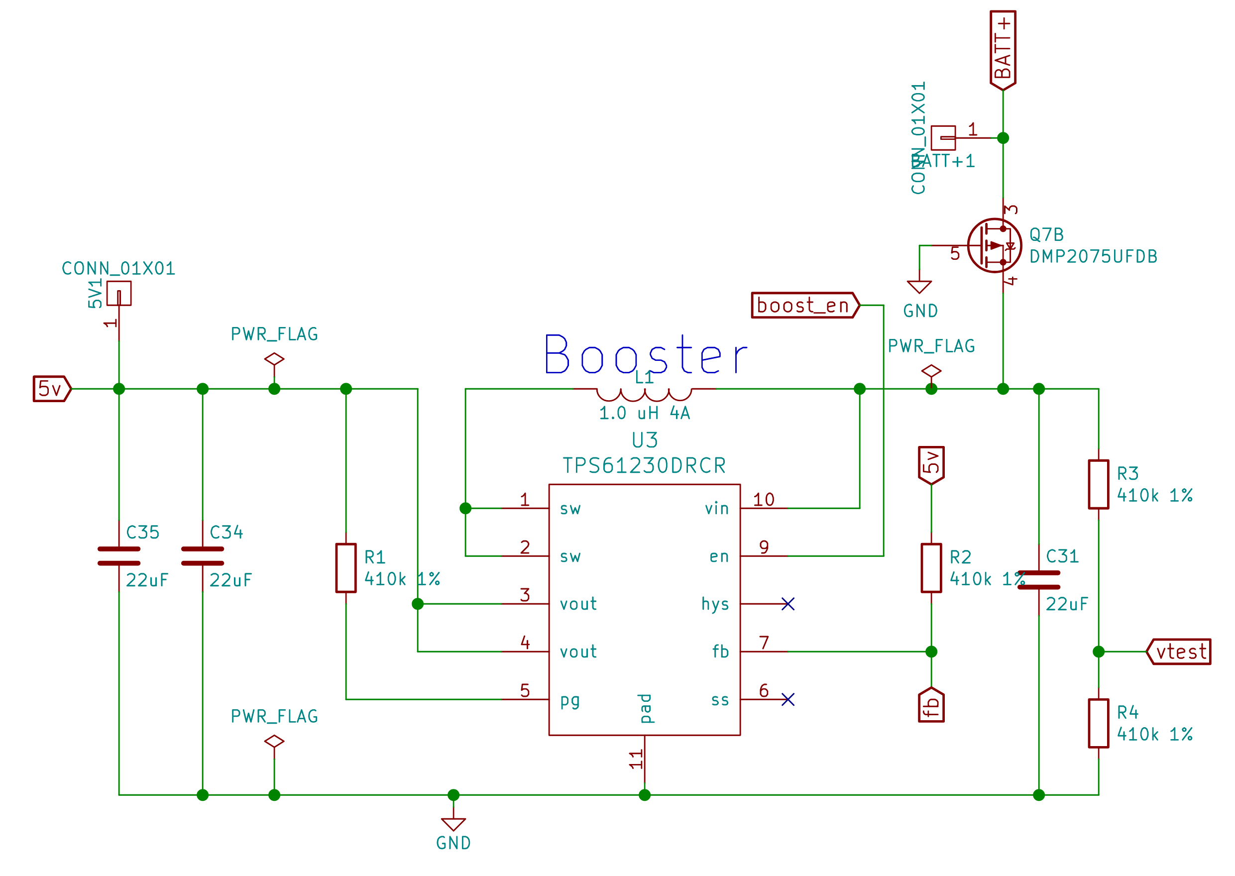
Now, it could be one of the other components in the booster circuit that has a problem. Like maybe Q7, L1, some of the capacitors or the voltage divider created by R2 and RN5 (not shown in the diagram), but from the description, I would think that U3 is the most likely culprit.
Not sure if this qualifies as an “easy” fix or not…
If this all seems to complicated, you could always just bridge the 5V and BATT+ pads. You will loose some volume by doing this, but the sound will function properly.
thank you for the help and advice (complete with schematic and explanation)
I will look on acquiring the relevant items as I’m sure I will use them in other areas.
if I bridge the 5v and batt + I assume this will not do any lasting harm and is therefore reversible?
was thinking of doing this while I wait for the parts to arrive.
It’s possible that the booster will work harder to try to raise the voltage that way. It’s usually only done when the booster is completely busted, so I don’t really know if it will cause any problems.
Generally, the easy to tell if if there is a problem is to check for heat. If nothing gets heat, it’s probably fine.
I didn’t end up bridging the 5v pad in the end as I’ve been very busy with work and holiday and wot not so nothing to report on that… though I might still give it a shot and see what happens.
Reducing the font track Db level worked reasonably well for a while but I think the 5v booster is slowly giving up so the bad distorted sound is back.
I have though ordered 3 5v booster chips to repair my board and have a couple spare for future use.
I also got a hot air solder station to alow my to do the repair.
Next is my questions.
I obviously need flux and solder that is suited to this repair and not as I understand it the standard stuff i already have.
So as you guys already know what works, I would like to ask you…
What do you recommend?
Liquid flux? … gel flux?
Reball solder paste?
You need solder paste. It has flux in it.
I would get it from a DIY site, like adafruit, sparkfun or oshstencils. They all have good options, and I’m not enough of an expert to say which is actually better.
Also, if you don’t have it already, I highly recommend some sort of magnification so you can see what’s happening properly.
Something like this. I’ve had good success with LEDs to PCBs with 63Sn/37Pb. I have 3 DIY Proffieboards in boxes on my to-do list and that’s what I figured I’d use. Although I see there are low temp melt versions which might be safer for the rest of the board. You’re going to want some Kapton tape for heat masking off the adjacent components so you don’t blow them off the board inadvertently.
A good hot-air soldering station can turn down the air flow to something sufficiently low that the components don’t blow off. (Unfortunately, I can’t recommend one, because the only good ones I know of are expensive…)
Mine goes pretty slow, but the small nozzle is wedged on semi-permanently, so that makes it faster than it should be, plus then if I tilt it up or it gets tapped, and I get these metal flakes flying out of it so…I can’t trust it too much. $40.