Blade Config

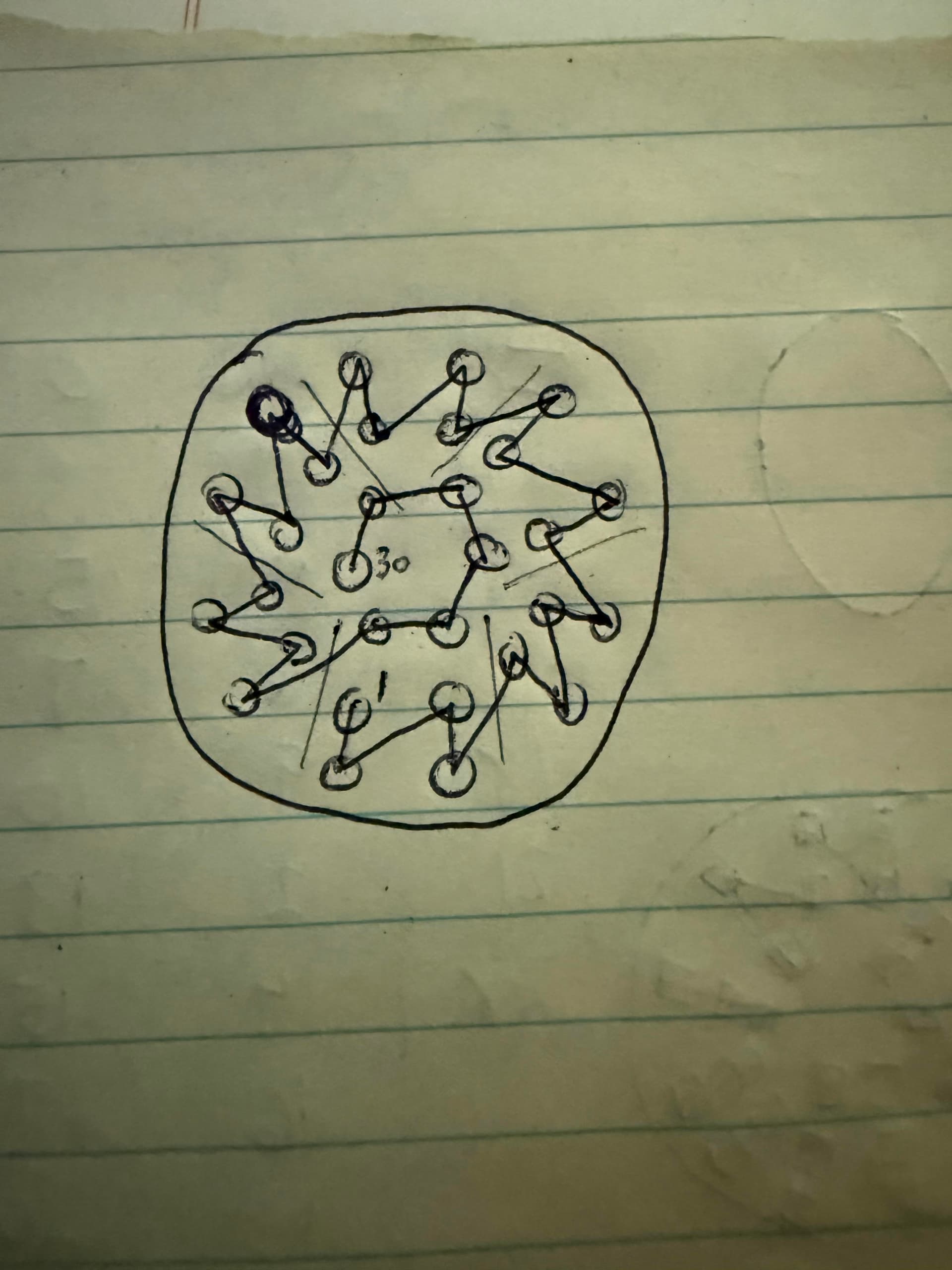
looking to start a build and the first time im using the ECO NPXL V4 Hilt Side PCB Connector. This PCB has 30 NPXL LEDs. the ones I’ve used before had much fewer. My quesstion is how do i identify all the LEDs in that PCB or do I even need to? Just not too sure right now.

The other “blades” are an accent strip and a crystal chamber which I already identified the number of NPXL LEDs.

BladeConfig blades[] = {
 { 0, WS281XBladePtr<144, bladePin, Color8::GRB, PowerPINS<bladePowerPin2, bladePowerPin3> >(),
    SubBladeWithStride(0, 15, 2, WS281XBladePtr<16, blade2Pin, Color8::GRB, PowerPINS<bladePowerPin2, bladePowerPin3> >()),
    SubBladeWithStride(1, 15, 2, NULL),
    WS281XBladePtr<20, blade3Pin, Color8::GRB, PowerPINS<bladePowerPin4, bladePowerPin5> >(),
    WS281XBladePtr<1, blade4Pin, Color8::GRB, PowerPINS<bladePowerPin1> >()
  , CONFIGARRAY(presets) },


};

Yes you do need to. If not, the rest will not illuminate.

This is for a PCB with 16 leds:
    SubBladeWithStride(0, 15, 2, WS281XBladePtr<16, blade2Pin, Color8::GRB, PowerPINS<bladePowerPin2, bladePowerPin3> >()),
    SubBladeWithStride(1, 15, 2, NULL),
This is for a PCB with 30 leds (on two rings):
    SubBladeWithStride(0, 29, 2, WS281XBladePtr<30, blade2Pin, Color8::GRB, PowerPINS<bladePowerPin2, bladePowerPin3> >()),
    SubBladeWithStride(1, 29, 2, NULL),

PCB with 30 leds on 3 rings (I assume, because I never used a 3 ring PCB):
    SubBladeWithStride(0, 29, 3, WS281XBladePtr<30, blade2Pin, Color8::GRB, PowerPINS<bladePowerPin2, bladePowerPin3> >()),
    SubBladeWithStride(1, 29, 3, NULL),
    SubBladeWithStride(2, 29, 3, NULL),


30 is for your number of LEDS
The first led is number 0 (zero)
The last led is number 29 (the 30th led)
2 is for “control one of every 2 leds”
3 is for “control one of every 3 leds”

0, 1 or 2 is “start with led number zero”, “start with led number one” or “start with led number two”

Thanks for the answer that makes sense. One last thing so I fully understand what do you mean by # of LEDs on # of rings? I guessing you are talking about inner ring, middle ring, outter ring of LEDs on a PCB.

Yes, exactly, but I have never seen a 3 ring PCB in person (or used one). In my code example above, I was assuming that they are wired like a 2 ring (inner & outer) PCB. But now you should be able to understand what the numbers mean.

If you do have 3 rings, don’t forget to add +1 to your NUM_BLADES and add one “middle ring” blade style in all your presets.

Edit: for your “3 rings” PCB, if the leds are not wired like a “2 rings” PCB, you might need to use SubBladeWithList

To figure out on what ring is each led on your PCB, you might want to try StylePtr<LengthFinder<>>(),

Make your PCB as one blade:

WS281XBladePtr<30, blade2Pin, Color8::GRB, PowerPINS<bladePowerPin2, bladePowerPin3> >(),

Follow the LengthFinder “procedure”, note which led lights up, in which order and on which ring. Then you can put those led numbers in your lists for your 3 rings.

It does have 3 “rings” but it isn’t completely filled.

On the the smallest ring, there is 2 there, 2 not going around.

Yea I’m trying to find a diagram on how this thing is wired. I feel like it would really help me get these LEDs configed differently from the actual blade itself.

I dont see a diagram for the exo, but it looks to me that it is like the standard v4. It hits a low pixel then moves up that line like a sun ray, then to the bottom of the next ray counter clockwise.

that is what I saw for the non Eco version. I guess im going to have to play around with the the Blade config to figure out where it starts the sequence. Thank you guys for the help.

A buddy of mine has this same pcb and he sent me a slowno video of the pcb this rough drawing is the order that the LED illuminated in.

Oh, interesting! Good to know

my understanding of this now this is what I came up. Gonna give it a try.

BladeConfig blades[] = {
 { 0, WS281XBladePtr<144, bladePin, Color8::GRB, PowerPINS<bladePowerPin2, bladePowerPin3> >(),
    SubBladeWithStride(0, 23, 2, WS281XBladePtr<30, blade2Pin, Color8::GRB, PowerPINS<bladePowerPin2, bladePowerPin3> >()),
    SubBladeWithStride(1, 23, 2, NULL),
    SubBlade(24,29,NULL),
    WS281XBladePtr<20, blade3Pin, Color8::GRB, PowerPINS<bladePowerPin4, bladePowerPin5> >(),
    WS281XBladePtr<1, blade4Pin, Color8::GRB, PowerPINS<bladePowerPin1> >()
  , CONFIGARRAY(presets) },
};

Here is a useful Blade Style Editor tool by @NoSloppy , it shows the connector pcb leds and numbers (Choose your pcb in the bottom left drop down menu): ProffieOS Style Editor

1 Like

Per my quick mental “math” your blade config should be good (if the diagram is accurate)