Howdy folks! Just installed a Graflex Supreme from Korbanth using a v3 Proffieboard.
I dry fitted the components before trimming all the wires down and installing into the hilt and things seemed to work as expected. I then desoldered everything from the board, got everything tidy in the hilt and I’m presented with this problem.
When the saber powers on, it says “Low battery” and it sounds distorted. The serial monitor is reporting 4.09v on the battery.
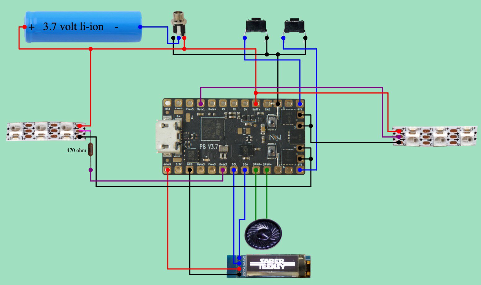
Note that this chassis uses a non-removable battery and a 2.1mm charging port. I followed the wiring diagram shown here in combination with the output of the Proffieboard V3 configuration tool:
I will have another look at this after work, but my first comment is that you can’t really rely on the voltage measurements in the serial monitor on a V3 board since the battery will be charging at that time. Disconnect the USB and use a multimeter to measure the battery voltage instead.
Little update. I’ve disconnected the Battery+ and Battery- wires from my board. I’ve measured the voltage between the wires from the positive and negative battery leads and it read 4.24v.
With the charger unplugged, I also measured the voltage between Battery+ and the recharge port’s “board” wire and I also got 4.24v.
After taking those readings, it seemed to me like the battery was fine, so I started to put it back in the chassis. I then heard evidence of a low battery again.
Once again, I measured with the multimeter and I got 1.35v this time. I took off the cover hiding the protection circuit on the battery and measured between the positive and negative pads: 4.24v.
Then I measured between the positive and “-p” pad and it read 1.35v.
So… I’m guessing this means something in the protection circuit is not working like it should. Like you suggested, I’m leaning towards replacing the battery at this point.
I’m not sure what the -p pad is, but it seems like you’ve found the culprit here.
Although, I suppose it’s possible that the protection circuit is actually protecting, which would mean that the problem is actually a short somewhere…
Spot on! I think there is something going on to cause the battery to protect itself. That said, I’m thoroughly confused now.
I’ve disconnected everything from the board apart from Battery+, Battery-, Speaker+, and Speaker-, but I’m still getting funky results. I can get to a point where the Battery+ and Battery- pads on the Proffieboard read 4.24v, but the audio still sounds distorted and I get the occasional battery low warning.
I’ve considered that the speaker could be bad, so I connected a spare that I had and I get the same distorted sound.
I’ve double checked my soldering on the board and I don’t see any places where things are touching that shouldn’t be.
One more test I’m going to do is measure the voltage between the Battery+ and 5V pads while audio is playing. I seem to remember reading elsewhere that could point to issues with a voltage booster?
Am trying to figure out something like this with one of my sabers which is a fully charged battery reads as 50% and drains dead in two weeks, so following this also in case your results gives me a hint
That said, in an attempt to eliminate wiring variables, I currently have just the battery and speaker wired up directly to the Proffieboard. With the board plugged in via micro USB, the battery should charge, right?
Right now my Mac computer isn’t recognizing the board, so I wonder if that’s just because the battery is depleted (it was only reading 2.4v before I plugged it in) or if there is some sort of cutoff in place while the batter is charging. I know that then the recharge port is wired in the board will shut off when the charger is connected.
Thank you for all the help and troubleshooting so far!
Well, I ended up wiring the recharge port back in because charging via USB was insanely slow, if it was charging at all.
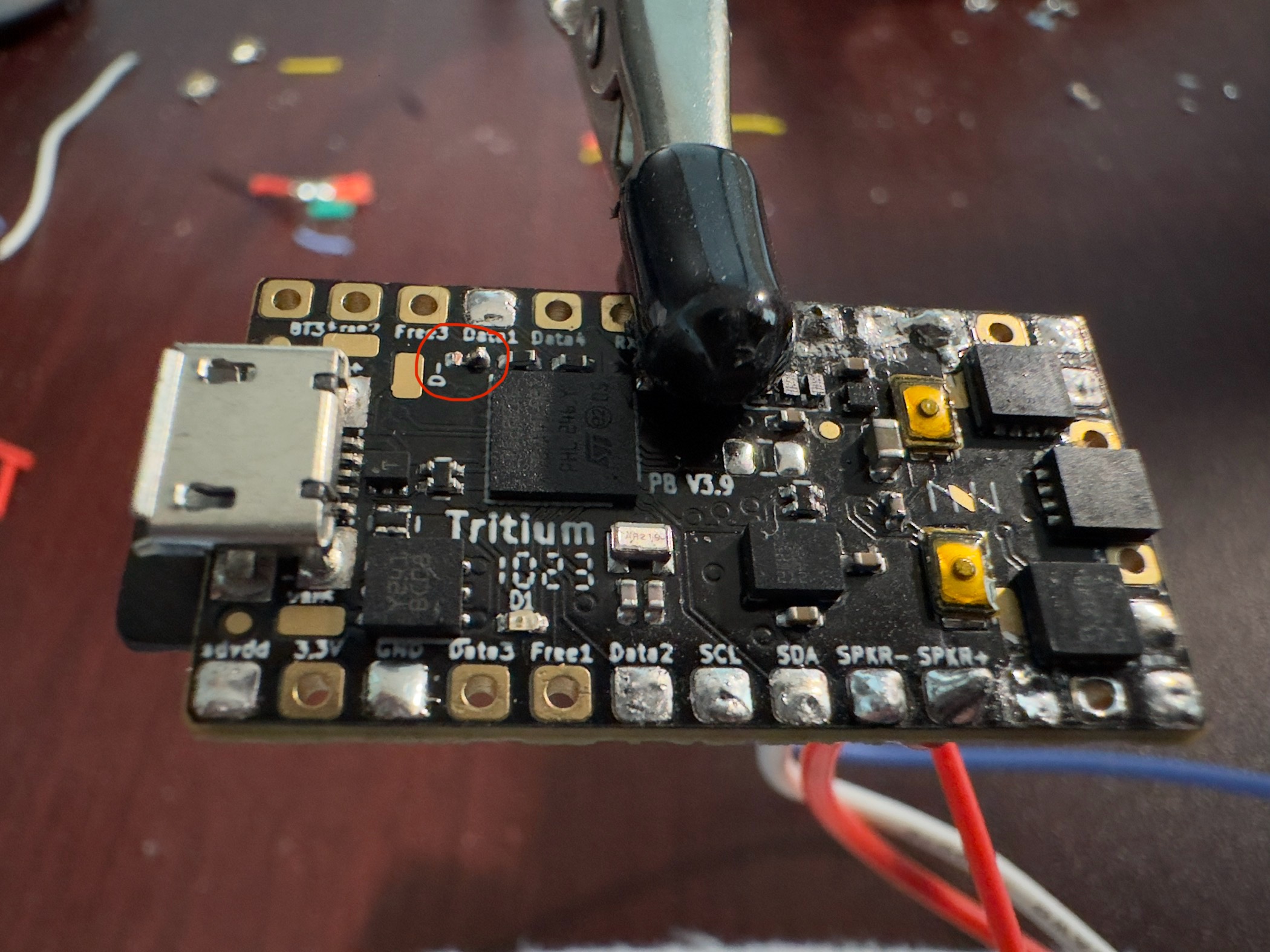
That said, I’m still getting funky results. I started inspecting the board further and I discovered something interesting. Is there supposed to be a resistor or something in the circled area of this photo?
Good grief. Thanks for the confirmation. I have no idea how that could have happened. Sure, the data pad is nearby, but it wasn’t by any means “tricky” to solder. I tried to look at some of the architecture docs to figure out what it does, but it’s all a little over my head. Maybe Fredrik can chime in and give some details about what the values of the resistor are what it’s for.
You’re in luck, the missing component is C5, which is a capacitor which is only used when you’re using touch buttons. If you’re not using touch buttons, then missing this component has no effect.
Nice! Not too worried about that then. Do I need to bridge those two contacts at all? Unfortunately that still leaves me wondering what on the board is causing the battery to go into protection mode. Side note, the board isn’t even powering on when connected to USB now…
How are the D series diodes looking? They’re 3 in a row right beneath BATT(+) and 5V pads, one is under your clip in the pic.
That whole area has some “scuz” around it, maybe clean it up and make sure there’s no shorts? You could also test the diodes if you have a multimeter with diode testing mode.